
Connectors
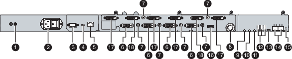
- Additional protective earth pin
- Input power connector
- RS-232 connector
- Switch (between RS-232 & Ethernet)
- Ethernet connector for monitor remote control
- DVI-D single link / dual link connector (**)
- +5Vout connector
- Headphone out connector (*)
- Mic in connector (*)
- Audio line out connector (*)
- Audio line in connector (*)
- USB connector type A (3) (*)
- USB connector type B (*)
- Ethernet connector (SFP+) cage (2) for optical network interface of 10Gigabit (*)
- Push button (*)
- DisplayPort connector
- DVI splitter output connector
- DVI splitter input connector
(*) Nexxis OR functionality: for more detailed information on Barco's Nexxis integrated OR solution please refer to the dedicated user guides. Please visit my.barco.com to obtain these user guides.
(**) 4 DVI connectors, numbered from 1 to 4 from right to left; all connectors must be installed when in SL mode; DVIs 1 & 3 or 2 & 4 must be installed when in DL mode.
