Connectors
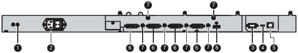
- Additional protective earth pin
- Input power connector
- RS-232 connector
- Switch (between RS-232 & Ethernet)
- Ethernet connector for monitor remote control
- DVI-D single link / dual link connector (*)
- +5V out connector
- DisplayPort connector
- DVI splitter output connector
- DVI splitter input connector
(*) 4 DVI connectors, numbered from 1 to 4 from right to left; all connectors must be installed when in SL mode; DVIs 1 & 3 or 2 & 4 must be installed when in DL mode.