4.1.7 Scheimpflug adjustment

Note: Always use allowed and calibrated lenses for the specific projector while adjusting the Scheimplug adjustments.
What has to be done ?

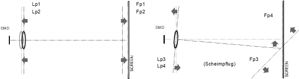
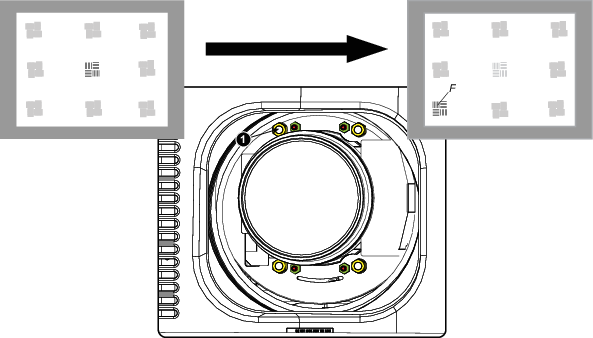
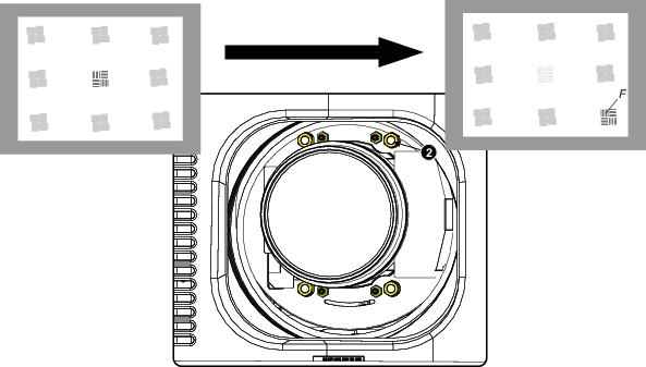
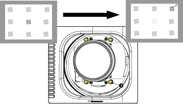
The lens holder has to be adjusted so that the “sharp focus plane” of the projected image falls together with the plane of the screen (Fp1→Fp2). This is achieved by changing the distance between the DMD plane and the lens plane (Lp1→Lp2). The closer the lens plane comes to the DMD plane the further the sharp focus plane will be. It can sometimes happen that you won't be able to get a complete focused image on the screen due to a tilt (or swing) of the lens plane with respect to the DMD plane. This is also known as Scheimpflug's law. To solve this the lens plane must be placed parallel with the DMD plane. This can be achieved by turning the lens holder to remove the tilt (or swing) between lens plane and DMD plane (Lp3→Lp4).

Image 4–25 Scheimpflug principle
Scheimpflug principle
The "plane of sharp focus" can be changed so that any plane can be brought into sharp focus. When the DMD plane and lens plane are parallel, the plane of sharp focus will also be parallel to these two planes. If, however, the lens plane is tilted with respect to the DMD plane, the plane of sharp focus will also be tilted according to geometrical and optical properties. The DMD plane, the principal lens plane and the sharp focus plane will intersect in a line below the projector for downward lens tilt.
Scheimpflug adjustment points
Image 4–26 Scheimpflug adjustments
Indication on drawingFunction
4Locking nut
1, 2 and 3Scheimpflug adjustment nuts
A, B, C and DSet screws
a, b, c and dlock nuts

1, 2 and 3 are adjustment points.

4 is a locking point and NOT used during Scheimpflug adjustment.

Required tools
How to adjust
  1. Project a green focus pattern.

    Image 4–27
  2. Loosen the lock nuts (a, b, c and d). See Image 4–26.
  3. Loosen the 4 set screws (A, B, C and D) by 1 cm. See Image 4–26.
  4. Fully loosen lock nut 4. See Image 4–26.
  5. Optimize the focus of the projected image as follows:

    1. Place the zoom lens in TELE position (smallest projected image) and adjust the focus using the lens focus barrel or motorized focus control.
    2. Place the zoom lens in WIDE position (largest projected image) and adjust the focus by turning equally on nut 1, 2 and 3.
    3. Repeat steps “a” and “b” until the projected image is as sharp as possible.
    Image 4–28 Center focusing
  6. Sharpen bottom left corner of the screen by adjusting nut 1.

    Image 4–29 Left bottom focusing
  7. Sharpen bottom right corner of the screen by adjusting nut 2.

    Image 4–30 Right bottom focusing
  8. Sharpen top right corner of the screen by adjusting nut 3

    Image 4–31 Corner focusing
  9. Repeat from step 6 until the projected focus pattern is as sharp as possible in the center, left, right, top and bottom of the screen.
How to fix the Scheimpflug

Start the fixation as follows (steps must be followed strictly) :

  1. Turn in set screw A, B and C. Tighten lightly (by hand).

    Tip: Any movement of the image will affect the Scheimpflug adjustment
  2. Fasten lock nuts a, b and c.
  3. Turn in set screw D lightly (by hand) allowing the image to move slightly (1/3 to 1/2 of a square).

    Image 4–32
  4. Fasten lock nut d.
  5. Tighten nut 4 until the offset of the image movement created in step 3 is canceled.

    Tip: The amount of image movement in steo 3 will determine how tight the nut in step 5 will need to be turned to return the image to its original position.