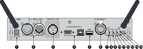
12 V output, maximum 1A, available when projector is not in stand by.
DMX interface
DMX is used as communication bus between different devices in the light technic. Each device has an input and an output, so that the bus can be looped between the different devices. According the standard a five wire cable with XLR connector is used.
You can use the DMX input port to connect a DMX device (DMX console) to the projector. This way you can control the projector from that DMX device (console). The DMX output port can be connected with the next device in the loop.
Pin
Description
1
Earth
2
Cold
3
Hot
4
Return - (or not used)
5
Return + (or not used)
DMX
DMX-512 Lighting protocol over RS-485 interface. Carries information of 512 channels from a lighting controller to lighting devices. Standardized by USITT.
Wired remote control (XLR)
If desired the remote control unit can be wired and plugged in into the male XLR port on the communication interface.
XLR – Remote CTRL in
Pin
Description
1
GND
2
RC5 in
3
XLR present sense
RS232/RS422 input
The communication interface of the HDX projector supports RS232 and RS422 serial communication on two different types of input connectors. The left one a Sub-D connector, the right one an USBB connector acting as RS input when connected to an USB input of a PC.
You can use the RS232/RS422 input to connect a local PC to your HDX projector. By this way you can configure and control your HDX projector from your local PC.
Note: Do not forget to set the projector's baud rate to match that of the computer.
Advantages of using RS232/RS422 serial communication:
easy adjustment of the projector via PC (or MAC).
allow storage of multiple projector configurations and set ups.
wide range of control possibilities.
address range from 0 to 255.
sending data to the projector (update).
copying data from the projector (backup).
RS232/422 input (Sub-D) port
Pin
Description
1
DCD : Data Carrier Detect
2
RXD- : Receive Data
3
TXD- : Transmitted Data
4
DTR : Data Terminal Ready [RS232]
TXD+ : Transmitted Data [RS422]
5
GND : Ground
6
DSR : Data Set Ready [RS232]
RXD+ : Received Data [RS422]
7
— (not connected) —
8
CTS : Clear To Send
9
RI : Ring Indicator
RS232
An Electronic Industries Association (EIA) serial digital interface standard specifying the characteristics of the communication path between two devices using either D-SUB 9 pins or D-SUB 25 pins connectors. This standard is used for relatively short-range communications and does not specify balanced control lines. RS-232 is a serial control standard with a set number of conductors, data rate, word length and type of connector to be used. The standard specifies component connection standards with regard to computer interface. It is also called RS-232-C, which is the third version of the RS-232 standard, and is functionally identical to the CCITT V.24 standard. Logical '0' is > + 3V, Logical '1' is < - 3V. The range between -3V and +3V is the transition zone.
RS422
An EIA serial digital interface standard that specifies the electrical characteristics of balanced (differential) voltage, digital interface circuits. This standard is usable over longer distances than RS-232. This signal governs the asynchronous transmission of computer data at speeds of up to 920,000 bits per second. It is also used as the serial port standard for Macintosh computers. When the difference between the 2 lines is < - 0.2V that equals with a logical '0'. When the difference is > +0.2V that equals to a logical '1'..
USB port
The communication interface is equipped with a master USB port, type “A” connector. This USB port will simplify the service procedures for software updates or for taking backup files from the projector without network connection. An USB-stick is plugged into the USB port and files can be transferred from or to the projector using the local or remote control unit. Note that the USB-stick has to be Linux FAT16 compatible.
Ethernet port
The projector can be connected to a LAN (local area network) using the Ethernet port on the communication interface. Once connected to the LAN, users are capable of accessing the projector from any location, inside or outside (if allowed) their company network using the control software: Projector Toolset. This toolset locates the projector on the network in case there is a DHCP server or the user can insert the correct IP-address of the projector to access the projector. Once accessed, it is possible to check and manipulate all the projector settings. Remote diagnostics, control and monitoring of the projector can then become a daily and very simple operation. The network connectivity permits to detect potential errors and consequently improve the time to servicing.
Note: The connector used for the Ethernet ports (E) are of rugged Neutrik EtherCon RJ45 type, which is compatible with standard RJ45 cable connector. Straight (most common) as well as cross linked network cables can be used.
10/100 Base-T — RJ45 port
Pin
Description
1
TXD+
2
TXD-
3
RXD+
4
—
5
—
6
RXD-
7
—
8
—
Status lights
Function
Color
Description
ETH act
green
When connected with an Ethernet
10/100
orange
When a 100 MB network is detected
IR
red
IR received but not acknowledged
green
IR received and acknowledged
WIFI sel
orange
When WiFi is selected
ACT
green
When WiFi is connected with an Ethernet
ERR
red
See chapter “Getting started”, topic “Status LEDs”
PWR
orange
See chapter “Getting started”, topic “Status LEDs”
LMP
orange
See chapter “Getting started”, topic “Status LEDs”