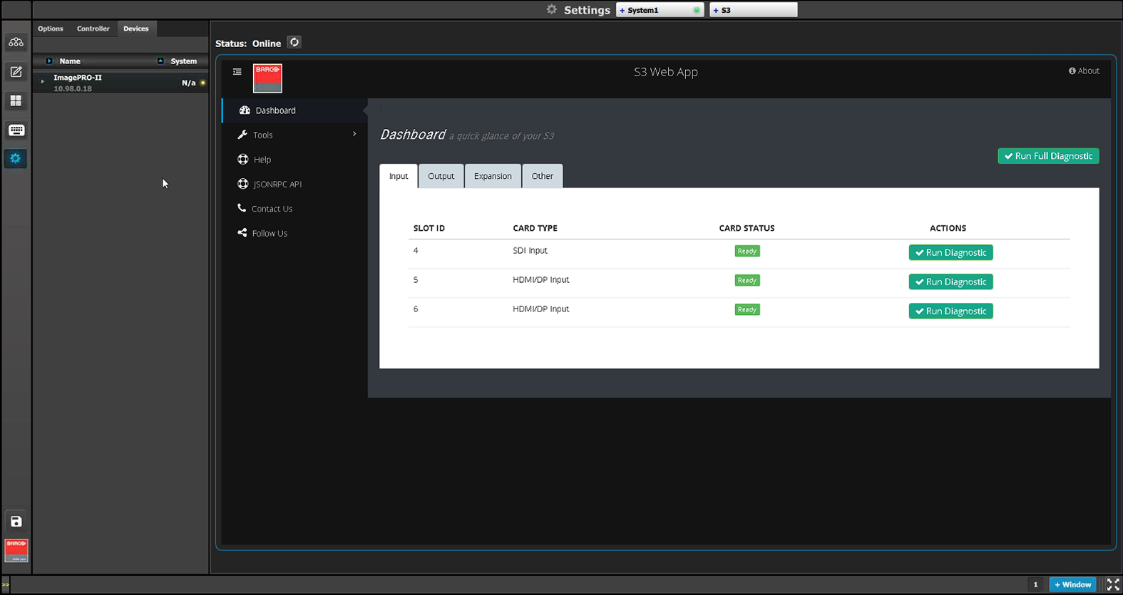
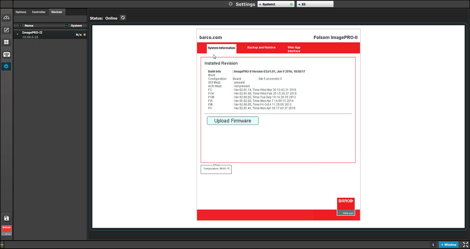
The Settings menu provides access to the Event Master series processor web app that is built into the unit. The app provides users with diagnostic reports, includes an FAQ section and contact information and supports system backup / restore and new firmware installation.
Description
This menu is accessible by clicking the System Settings icon on the menu bar on the left side of the UI.
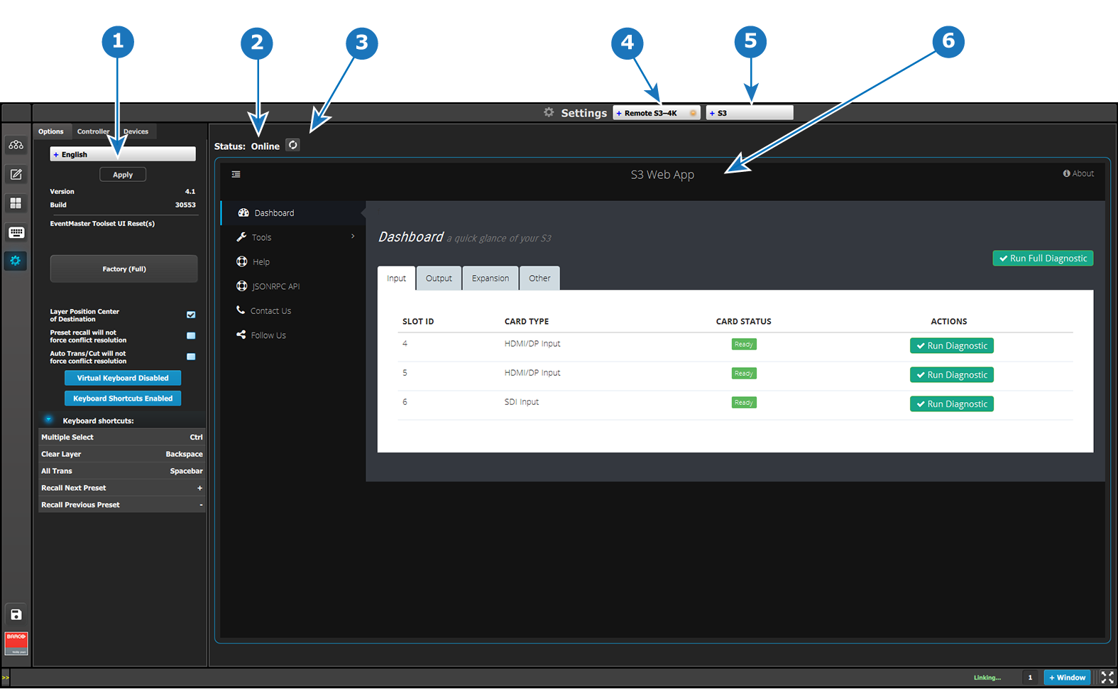
Image 6–116Settings Menu
1
Resources area
The Resources area contains the Options, Controller, and Devices tabs.
The Controller tab shows EC series controller settings and is applicable only when an EC series controller is connected on the network or to a computer running the EMTS.
The Devices tabs shows what Barco devices (such as projectors) are detected on the network.
The Option tab allows the user to choose settings concerning the Event Master Toolset Software.
Please see the sections below dedicated to these options.
2
Status
Show status:
Online: the VP is online and the web application can be reached.
Web application error: the VP is online but the web application cannot be displayed.
Offline (in red text): the VP is offline.
3
Refresh Web app area button
Similar to web browser, pressing this button will trigger an attempt to refresh / reconnect to the web interface of the selected VP.
4
System select combo box
Informs the users which System is currently being selected. If there is more than one System defined in the UI, this combo box can be used to select between the different Systems.
5
Device select combo box
Informs the user which Device is currently being selected in the current system.
6
Web app area
Main work area where the different menus are displayed.
Description of the Options tab of the Resources area
Language: This parameter allows the user to choose the language of the GUI.
Note: The only languages available are English and (Simplified) Chinese.
Version: version number of the Event Master Toolset (read only).
Build: build version of the version of Event Master (read only).
Event Master Toolset UI Reset(s)—Factory (Full): A Factory (Full) reset deletes all information and returns the UI to factory settings, removes all added systems from the configuration page, clears the input thumbnails and any Programming page layouts, and returns to default all choices on the settings page.
Layer Position Center of Destination: Coordinates for PIP’s and Destination’s origin is (0,0) positioning. Allows the user to choose the default layer position.
If selected the position X=0 and Y=0 will be in the center of the destination and Pixel 0 will be in the center of the PIP.
If unselected the pixel X=0 and Y=0 will be on top left of the destination and Pixel 0 will be on top left of the PIP.
Preset recall will not force conflict resolution: When this box is checked, conflict resolutions are not forced when recalling a Preset. A pop-up window appears, requiring user confirmation. The user’s choices are:
Resolve–All Trans
Resolve–Cut
Resolve–Wait
Cancel
Auto Trans/Cut will not force conflict resolution: When this box is checked, conflict resolutions are not forced when either the All Trans button or the Cut button is activated.
Show ToolTip: This button turns On or Off the ToolTips.
Keyboard Layout: This button allows a choice between QWERTY and AZERTY keyboards.
Virtual Keyboard: This button enables or disables the virtual (on-screen) keyboard. This is useful when the EMTS is running on a device that employs a touchscreen monitor, and there is no hardware keyboard available for typing.
Keyboard Shortcuts: This button enables or disables keyboard shortcuts.
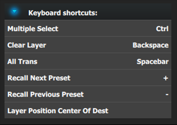
Keyboard shortcuts list: The following keyboard shortcuts are available in the Event Master Toolset software.
Image 6–117Keyboard shortcuts list
It’s possible to change any shortcut key:
Double click on the shortcut name (e.g. Multiple Select).
A popup appears near the shortcut name.
Press any key on the keyboard.
This key will affect to the selected shortcut.
Description of the Controller tab of the Resources area
The Controller tab shows EC series controller settings and is applicable only when an EC-30, EC-50 or an EC-200/EC-210 controller is connected to the system. The Controller tab has three subtabs: Software, User Pref, and Diagnostic.
Software subtab
Controller tab: Software subtab
This panel displays the serial number and the software version for each detected controller.
When the Controller > Software subtab is selected in the Resources area, the Web App area shows the EC-200/EC-210 web app. The user can upgrade the EC-200/EC-210 software through this web app.
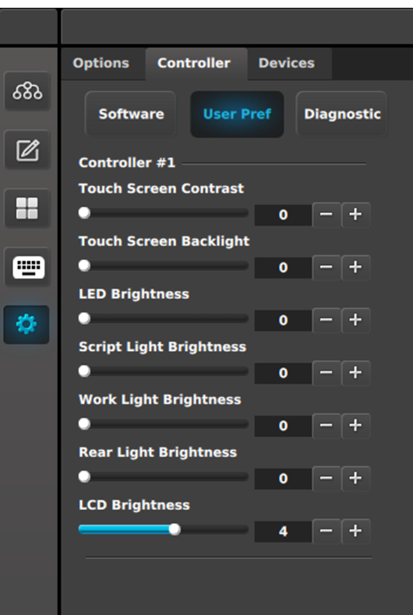
User Pref subtab
Controller tab: User Pref subtab
This panel displays the user-defined preferences for each detected controller. The user can also adjust the preferences in this panel.
Touch Screen Contrast: Change the contrast of the touch screen displays. Range is 0–100.
Touch Screen Backlight: Change backlight brightness of the touch screen displays. Range is 0–100.
LED Brightness: Change the brightness of the LEDs under the buttons. Range is 0–6000.
Script Light Brightness: Change the brightness of the LED script lights. Range is 0–16000.
Work Light Brightness: Change the brightness of the white LEDs on the front bottom of the controller. Range is 0–16000.
Rear Light Brightness: Change the brightness of the red LEDs on the rear top of the controller. Range is 0–16000.
LCD Brightness: Change the LCD display brightness. Range is 0–7.
Note: These controls are N/A on the EC-30 controller.
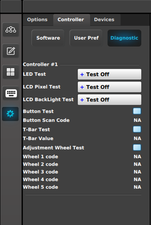
Diagnostic subtab
Controller tab: Diagnostic subtab
This panel displays test controls for each detected controller.
LED Test:
Test Off: LEDs are returned to normal behavior.
All Blue/Red: Turns on all blue and red LEDs; other LEDs are turned off.
All Green: Turns on all green LEDs; other LEDs are turned off.
LCD Pixel Test:
Test Off: LCD text is returned to normal behavior.
All: All LCD displays are filled (all 256 bits are enabled).
LCD Backlight Test:
Test Off: LCD colors are returned to normal behavior.
Red: Only LCD red color is turned on.
Green: Only LCD green color is turned on.
Blue: Only LCD blue color is turned on.
All: LCD red, green, and blue colors are all turned on.
Button Test:
Checkbox checked: The test is on.
When the test is on, do not trigger the behavior of the button. For example, if a button is mapped to a Preset, do not recall that Preset.
Button Scan Code: With the Button Test On, pressing a button on the controller shows the button number returned by the API (in place of the “NA”).
T-Bar Test:
Checkbox checked: The test is on.
T-Bar Value: Moving the T-Bar shows the number returned by the API as the T-Bar changes positions.
Adjustment Wheel Test: (EC-200/EC-210 only)
Checkbox checked: The test is on.
When the test is on, rotating the wheel shows the number returned by the API.
Description of the Devices tab of the Resources area
The Devices tab lists devices, such as projectors, that are available on the same network as the EMP. Devices such as other processors (E2, S3–4K, EX, etc.) are also displayed in this list.
Image 6–118Devices tab
Dragging and dropping any discovered device from the Resources area to the Web App area hosts the device (for example, an ImagePro II) in the Web App area.

 This menu is accessible by clicking the System Settings icon on the menu bar on the left side of the UI.