
14.28 Genlock Cable

Flow chart
Image 14–90
Note: The flat ribbon Genlock cable connects the Genlock Assembly to the System-Power board. This procedure provides instructions on how to disconnect the cable on both sides.
Note: Make sure the latches are fully engaged to prevent the cable from coming loose.
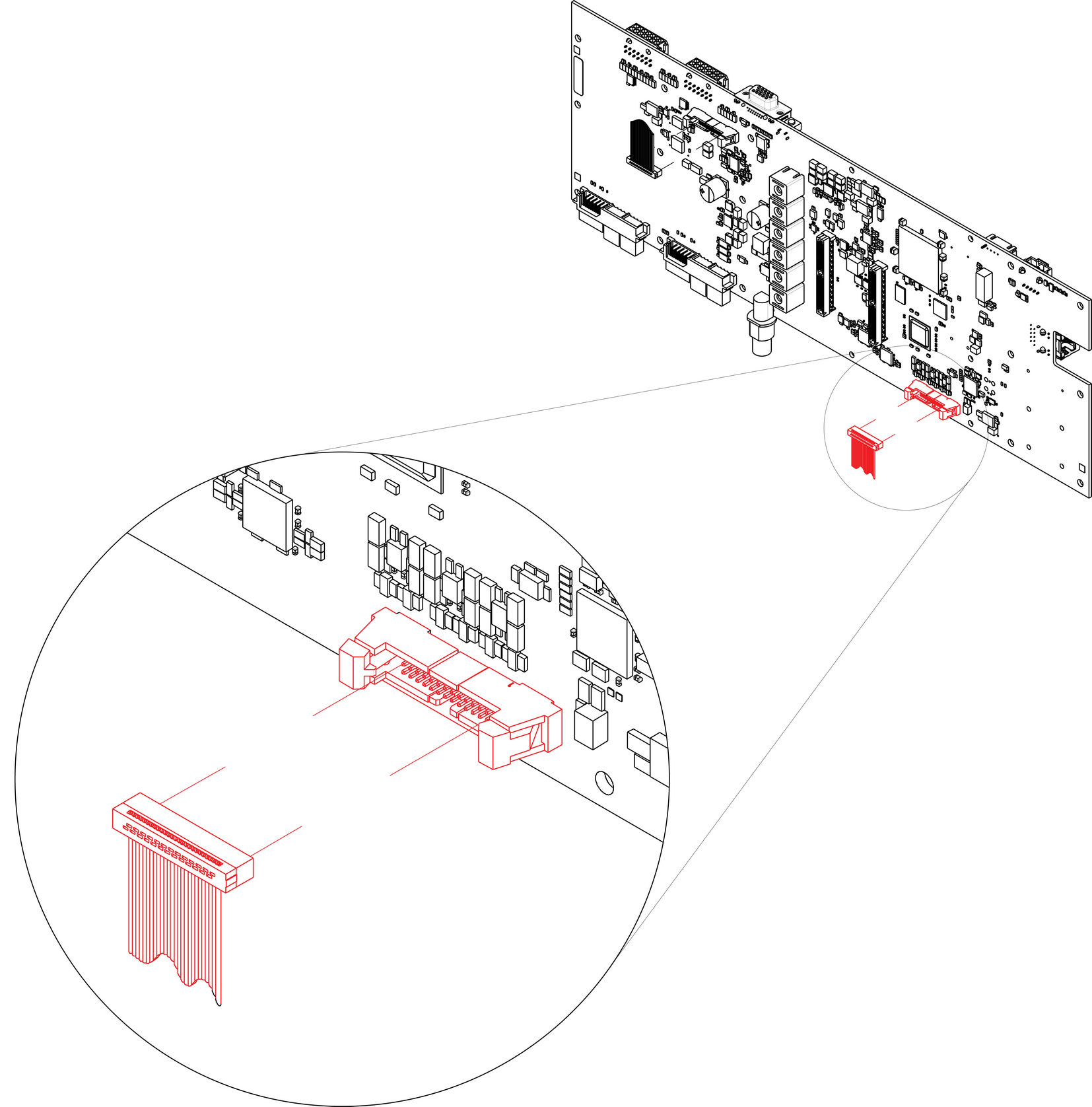
Concerned parts
Cable Kit Set
Necessary tools
How to remove the Genlock cable
  1. Remove the Genlock Assembly and disconnect the Genlock cable from the board. Follow the instructions as provided in the previous section.
  2. Turn the unit upside down and follow the steps detailed in other procedures to remove the Bottom Panel and the CPU module from the System-Power board.
  3. Remove the USB, VFD, 3RU and 1RU cables that are connected to the System-Power board.
  4. Remove the screws that attach the System-Power Board to the standoffs.
  5. Lift the System Power Board from the standoffs and flip it over, but don’t extend it too much.
  6. Unplug the side of the Genlock cable that is plugged into the System Power board.

    Image 14–91 Genlock-cable connector
    Note: Only the Gen 1 system card is shown, but this connection is the same on the Gen 2 system card.
  7. Remove the cable from the unit.
How to install the Genlock Cable

To install the Genlock Cable follow the same procedure in the reverse order.

Note: There is a key on the connector to prevent incorrect insertion of the cable.
Note: Make sure the latches are fully engaged to prevent the cable from coming loose.