6.15 Configuration Menu > Adjustment > Output Configuration
General
In the Output menu users can assign output connectors to configurations and adjust signal parameters to match the display devices connected to the unit.
Output Card arrangement
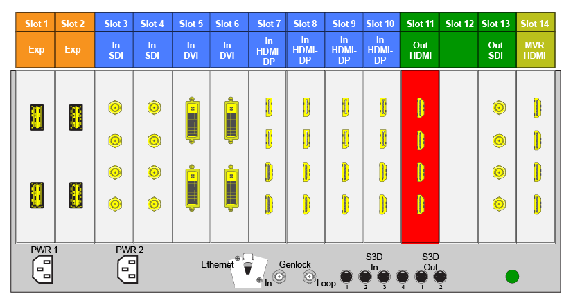
On the E2 model, the output cards occupy slots 11 through 13 and right justified to slot 13.
On the S3–4K model, the output cards occupy slots 7 through 8 and right justified to slot 8.
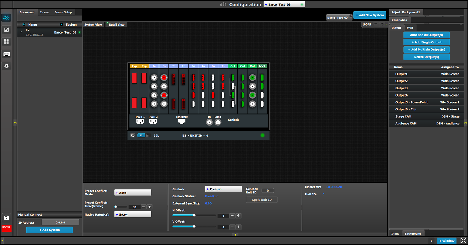
If there is an empty output slot, all output cards to the left of that empty slot will show as RED in the GUI. Red indicates that although the cards will operate properly, outputs from these cards will not be available at the Multiviewer.
Image 6–19E.g. E2 with an empty output-card slot
If the card with the connectors that are part of an output configuration is missing, the output configuration in the configuration list will be grayed out.
Also, if there is an existing output configuration but the card in the slot is of different type, then again the configuration will be greyed out.
Output Connector Grouping
The connectors can be grouped together to define a 3D* , 4K or Videowall configuration. For example, a projector that requires 2 DVI connectors to pass 3D Left and Right eye signals. Also 4 SDI connectors can be configured as a 4K output in order to connect to a 4K projector.
There are several rules that apply when defining an output configuration:
Each Output connector can only be assigned to one output configuration.
Outputs in an output configuration must be of the same type AND in the same slot or in adjacent slots. For example, there cannot be a HDMI connector and an SDI connector in the same output configuration.
Max connectors for an output configuration = 4.
Once output connectors are assigned to the same output configuration, all settings for the output connectors will be synchronized.
If an output connector is not assigned to an output configuration,
Output settings cannot be adjusted on that connector.
The connector cannot be assigned to a destination
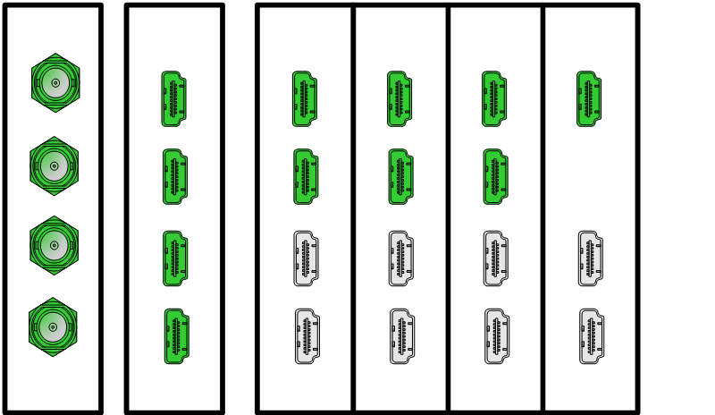
Examples of 4K Valid Outputs:
Image 6–20
4 x SDI 1920x1080
4 x HDMI 1920x1080 or 2048x1080 on 1 card
4 x HDMI 1920x1080 or 2048x1080 two cards
The top 2 x HDMI at 1920 x 2160 or 2048 x 2160 at max 60P
One of the top HDMI at 3840 x 2160 or 4096 x 2160 at max 30P
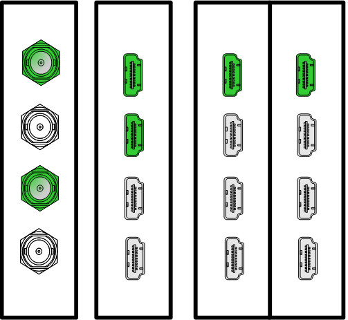
Examples of valid 3D Outputs *:
Image 6–21
(*) Future software release
Output connector colors
Not added to system as grouped connector or single connector
Assigned to any output configuration
Assigned to a screen or auxiliary destination
Output configuration menu description
Output configuration menu is accessed by clicking on the Output tab.
This menu provides:
Auto add all Output(s): A button to automatically allocate all unassigned output connectors to Output configurations.
+ Add Single Output: A button to manually allocate all selected output connector(s) to an Output configuration.
+ Add Multiple Output(s):A button to manually allocate more than one connector to an individual Output configuration per connector.
Delete Outputs: A button to delete unused or obsolete Output(s).
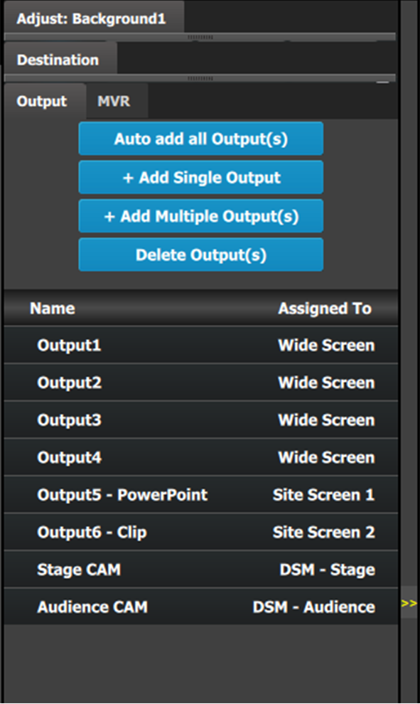
A list of all the Outputs already created on the system (e.g. Output1 and Output2).
How to Auto add Outputs
The “Auto add all Output(s)” button allows all 2K outputs that are not already assigned to an output configuration to automatically assign to individual output configurations. Output connectors that are already assigned to output configurations will not be affected. The picture below shows what occurs when the button is pressed. Since there are 12 output connectors not assigned, all 12 Output configurations are automatically assigned.
Since the software assigns automatically only 2K outputs, Dual link or 4K outputs need to be configured manually. See How to add output section below.
The unit will query the connected device on its output for a preferred EDID and try to assign that as the output resolution and frame rate. If no devices are connected, a standard HD resolution with the native rate of the EMP is assigned as frame rate.
Next to the configuration name is the name of the Destination where the output is assigned. If the Output is not assigned to any Destination, then the name will be “N/A”.
Note: The software by default names outputs as [ConnectorType] “Output 1, 2, 3...” The user can rename each output by double clicking on the name and type in the new name in the blue box.
How to add an Output
Output configurations can be added manually to unassigned connectors.
Select the Detail View tab in the system diagram area.
Select any unassigned connectors from the detail view.
Selected connector(s) will be highlighted blue.
Note: If the output is 4K provided by the quad SDI connectors, the 4 SDI connectors need to be selected.
Connector(s) is immediately highlighted in blue.
Click on either the Add Single Output or Add Multiple Outputs button, depending on if single or multiple connectors need to be added as a single output, or if multiple connectors are to be created as multiple outputs.
The created outputs are now added to the output list and can be further configured by individually selecting them, then using the adjust tab to make any necessary changes.
How to delete Output
Click on the Delete Output(s) button
The Delete Output(s) button is replaced by the Delete Selected button (highlighted in red).
Click on the corresponding connector in the graphical area.
or
click in the “x” on the right hand side in the output configuration list.
Connector(s) will be immediately highlighted in blue.
The deletion is completed by clicking the Delete Selected button.
Note: Multiple connector configurations can be selected to be deleted together.
Note: You can only delete Output Configurations that are not assigned in Destinations.
How to adjust output configurations
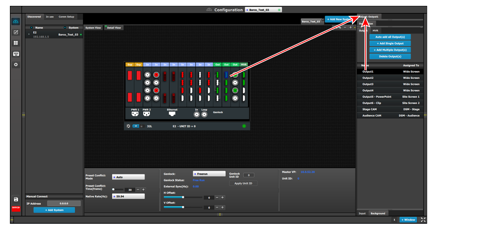
Adjustments to outputs are performed in the “Adjust” panel:
Select the output from the configuration list
or
click on the connector graphic.
An output is selected.
Click on the Adjust tab that is on the top of the Adjustment area.
Image 6–23Accessing the Output Adjust panel
The output adjustment panel is displayed.
Output adjustment panel description
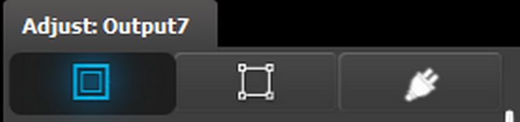
The output adjustment panel is divided in three sections
Main page
Format & Timing
Connector
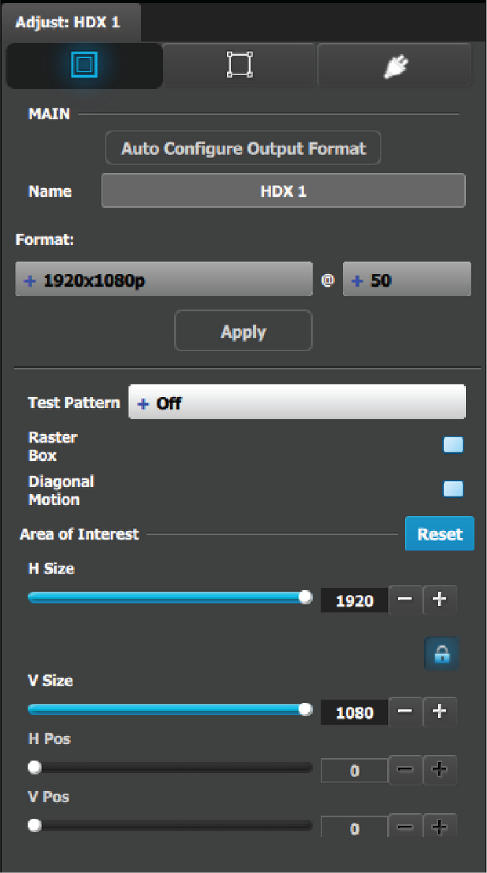
Output adjustment panel > Main page
Auto Configure Output format: Sets the output format to match the format contained in the EDID of the display device connected to the corresponding output(s).
Name: The name of the output configuration can be edited in this field.
Format: Selects the video format of the output configuration from the drop-down menu. The available formats are in compliance with the output connector capacity. For example, if the connector capacity is set to SL (Single Link), only single link formats will be presented in the drop-down menu.
Test pattern: Turns the Test Patterns ON and select the desired type. The default setting is OFF. Test pattern types :
Horizontal Ramp
Vertical Ramp
100% Color Bars
16x16 Grid
32x32 Grid
Burst
75% Colorbars
50% Gray
Horizontal steps
Vertical steps
White
Black
SMPTE Bars
H Alignment
V Alignment
H V Alignment
Circle Alignment
Red
Green
Blue
Raster box: Turns ON or OFF on a raster around the default active area. This raster box is a white, single-pixel-wide broken line.
Diagonal Motion: Turns the Diagonal Motion ON or OFF for select patterns
The motion is a bottom-right to top-left diagonal for 16x16, 32x32 grid
The motion is right to left for 100% Color Bars.
There is no motion in Horizontal and vertical Ramps and other patterns
Area of Interest (AOI): A raster box that can be positioned and sized within the outputs active area, it effectively makes the AOI the new active area.
This raster box is a green, single-pixel-wide broken line that helps you adjust the AOI within the output’s active area
The handles for the AOI menu are:
H Size and V size : Adjusts the horizontal and vertical positions respectively
H Pos and V pos: Adjusts the horizontal and vertical positions respectively
Note a lock button to allow user to lock the aspect ratio of the size.
Reset button: resets the AOI to default which is the full output area.
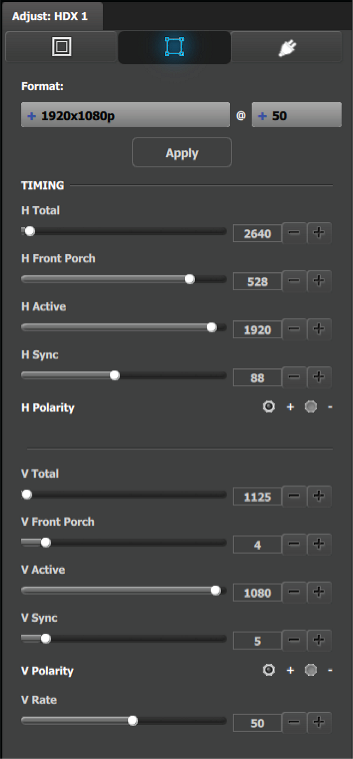
Output adjustment panel > Timing Menu
Format: Selects the video format of the output configuration from the drop-down menu. This is the same adjustment as in the previous menu.
H Total: Adjusts (in pixels) the total pixel count per line for the selected output.
H Front Porch: Adjusts (in pixels) the offset between the end of the output active area and the beginning of H sync.
H Active: Adjusts (in pixels) the horizontal size of the output active area.
H Sync: Adjusts (in pixels) the H sync width.
H Polarity: Adjusts the polarity (active High or Low) of the horizontal sync pulse (N/A in SDI).
V Total: Adjusts (in lines) the total line count per frame.
V Front Porch: Adjusts (in lines) the offset between the end of the output active area and the beginning of V sync.
V Active: Adjusts (in lines) the vertical size of the output active area.
V Sync: Adjusts (in lines) the V sync width.
V Polarity: Adjusts the polarity (active High or Low) of the vertical sync pulse (N/A in SDI).
V Rate: Adjusts the frame rate in seconds polarity (active High or Low) of the vertical sync pulse (N/A in SDI).
Note: Changing these values can make the video signal undetectable for other devices. Always use a VESA timing calculator for best results.
Output adjustment panel > Connector Menu
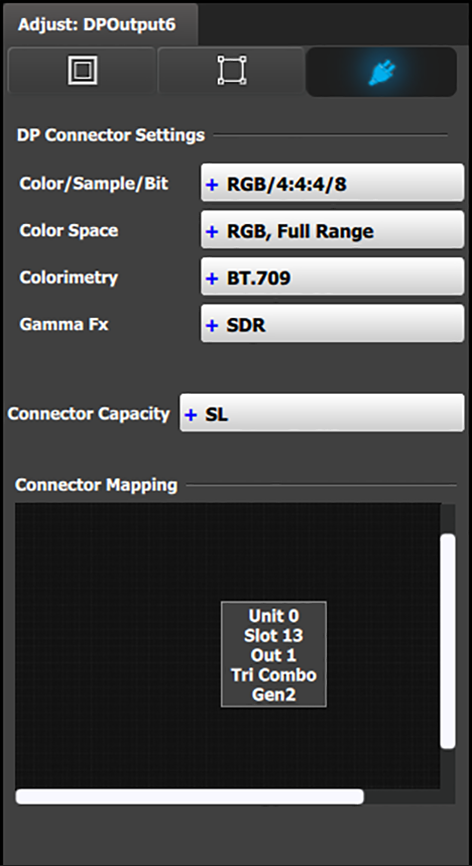
Connector Menu: Output Adjustment—DP
For DP 1.2 outputs:
Color/Sample/Bit: Adjusts the color space (RGB or YCbCr), sampling rate (4:4:4) and bit depth (8, 10, or 12) of the output signal.
Color Space: Adjusts the color range (RGB or SMPTE, Full or Reduced).
Colorimetry: Choose the colorimetry ITU-R recommendation for the output.
Available recommendations are:
BT.601 (SDTV)
BT.709 (HDTV)
DCI-P3 (digital movie projection)
Gamma Fx: Choose the Gamma format for the output.
The Gamma Fx value for DP connectors is SDR.
Connector Capacity: If the connector is not assigned to a Destination as above, the capacity can be changed. Once included in a Destination configuration this needs to be managed thru the Adjust pane of the Destination.
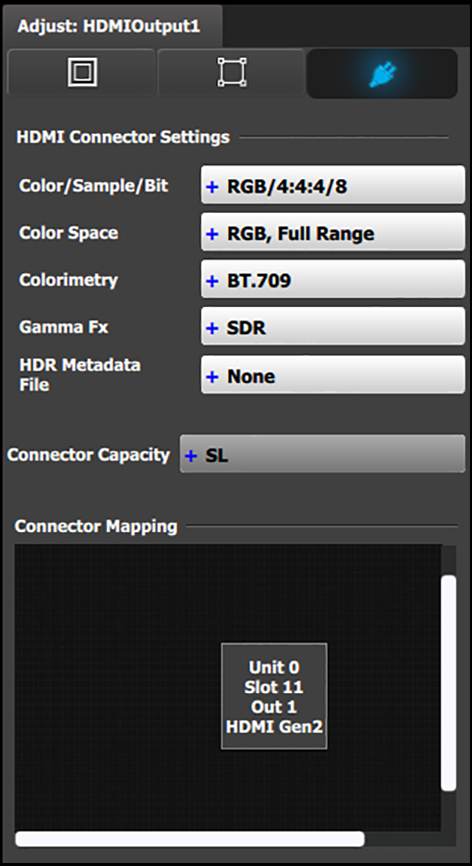
Connector Menu: Output Adjustment—HDMI
For HDMI outputs:
Color/Sample/Bit: Adjusts the color space (RGB or YCbCr), sampling rate (4:4:4 or 4:2:2) and bit depth (8, 10, or 12) of the output signal. Depending on the EDID of the connected device the drop-down list would populate with compatible settings.
Color Space: Adjusts the color range (RGB or SMPTE, Full or Reduced).
Colorimetry: Choose the colorimetry ITU-R recommendation for the output.
Available recommendations are:
BT.601 (SDTV)
BT.709 (HDTV)
BT.2020 (UHD) – (N/A for HDMI 1.4.)
DCI-P3 (digital movie projection) – (N/A for HDMI 1.4.)
Gamma Fx: Choose the Gamma format for the output.
Gamma Fx values are:
SDR
HLG
PQ/HDR10
Note: The only choice for HDMI 1.4 is SDR.
HDR Metadata File (HDMI 2.0 only): Choose the HDR metadata file for use with the PQ/HDR10 format.
Connector Capacity: If the connector is not assigned to a Destination as above, the capacity can be changed. Once included in a Destination configuration this needs to be managed through the Adjust pane of the Destination.
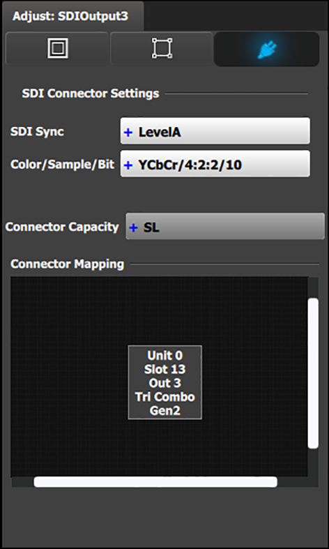
Connector Menu: Output Adjustment—SDI
For SDI outputs:
SDI Sync (available with SDI connector type) : allows a choice between HD (1.5Gb), 3G (3Gb) Level A, Level B, Level A 2SI, or Level B 2SI.
The SDI Sync options vary, depending on the format of the Outputs. For example, for:
NTSC/PAL—the SDI Type can be only SD.
1080i or 1080p, with a refresh rate less than or equal to 30 Hz—the SDI Type can be only HD.
1080p, with a refresh rate greater than 30 Hz—the SDI Type can be:
Level A (default)
Level B
Level A 2SI
Level B 2SI
The 2SI options are available only if the Input/Output configuration has 4 SDI connectors from the same card, and the Output format is either 1920 x 1080 or 2048 x 1080.
Color/Sample/Bit: Adjusts the color space (YCbCr), sampling rate (4:2:2) and bit depth (10) of the output signal.
Connector Capacity: If the connector is not assigned to a destination the capacity can be changed. Once included in a Destination configuration this needs to be managed thru the Adjust pane of the Destination.
Note: The selection of HD (1080i) or 3G SDI (1080P) actually happens when the format type is selected in the main tab.