General
In this procedure, you will add Outputs to the system .

In this procedure, you will add Outputs to the system .

Each connector has a capacity setting that assigns internal resources to the connector. In order to increase the capacity of an individual connector, you may first have to reduce, or disable capacity from other connectors on the same card. For example, if two Dual Link signals are required to be output on a HDMI 1.4 output card, the capacity of the two bottom connectors must first be set to "None."
If a connector is to be used to accommodate a 4K signal all other connectors on each card needs to be set to “NONE.”
3G-SDI Outputs can only output UHD/4K over a Quad connection.
If the Auto add all Outputs button is pressed, the software configures all previously unassigned output connectors as individual, single-connector outputs, in order, from top to bottom of each card, starting from left to right.
This button is a shortcut for systems using a large number of single-connector outputs.
If the Auto add live Output(s) button is pressed, the system adds an output for each of the single connectors, except for SDI, that is connected to an active display device, by reading its EDID and adjusting its connector capacity and output rate accordingly. These outputs are added in order, from top to bottom of each card, starting from left to right.
This is where you add specific output requirements in order to allow for the configuration of an individual output from a single connector or from multi-connectors. Typical multi-Connector output examples are Dual Link outputs of 3840x1080 or quad link SDI for UHD and 4K
Click on the desired output connector(s) in the diagram area to select the outputs that will be defined.
All connectors must be the same type and capacity, and the selection can be one, two, or four connectors, creating a max resolution of 4K.
Select more than one output connector and click the +Add Multiple Outputs button to create an individual output for each connector selected. This is a shortcut like the "Auto add..." buttons but limited to only the selected connectors.
Once all connectors are added they appear in a list directly under the Output Tab. It is recommended to name outputs based on the actual connection scenario instead of the connected devices function. This is due to several layers of naming that can be done in the system to simplify understanding during operation.
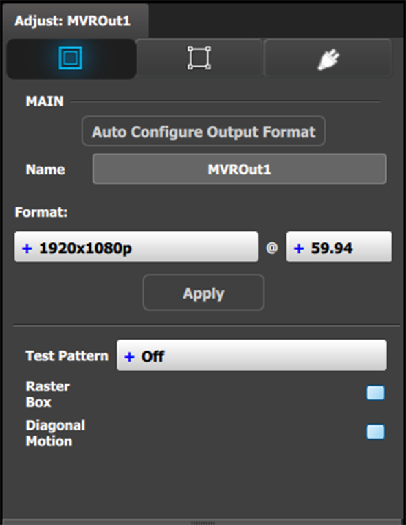
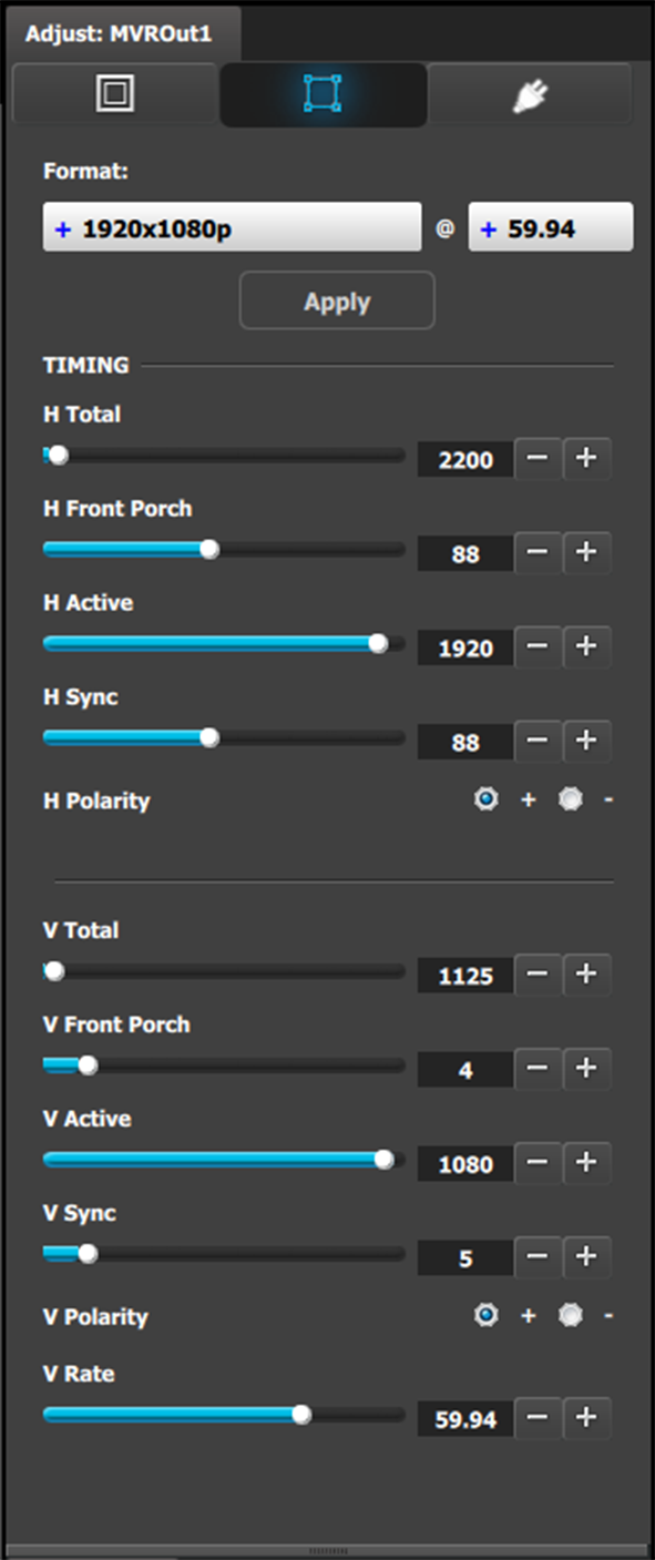
Click on the Adjust tab that is located on the top. The output adjustment panel is divided in three sections (Main, Timing, Connector). In the Adjustment panel you can:
[Main tab] Define the Area of interest (AOI).
[Timing tab] Read all timing parameters associated with the selected format and make adjustments.
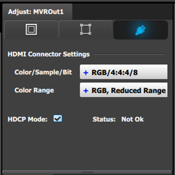
[Connector tab] Select HDCP Mode On or Off.
The default for all outputs is Off. To turn On the HDCP Mode, click on the empty checkbox. When the checkbox displays a check mark, HDCP Mode is On. HDCP Mode is not applicable to SDI outputs.