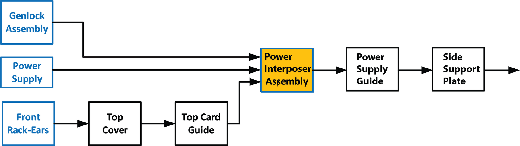
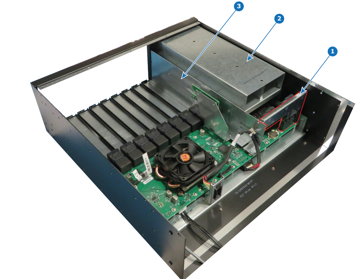
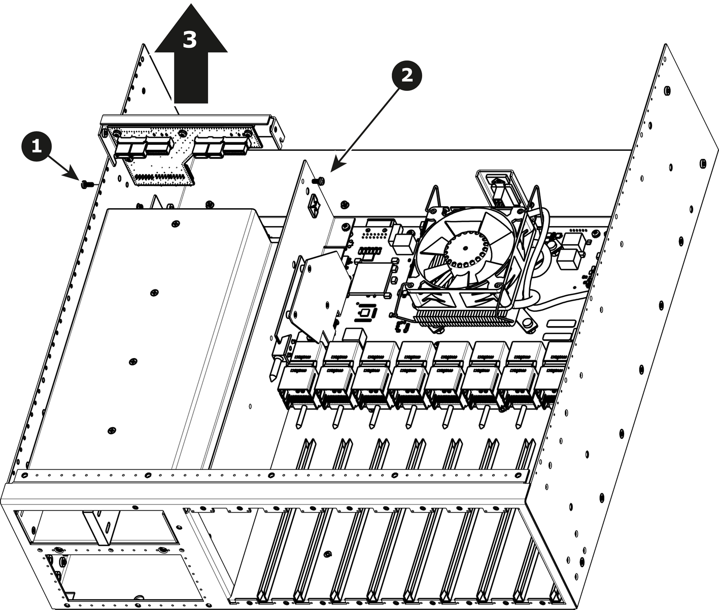
How to remove Power Interposer AssemblyRemove the pan head screw (4-40x0.25 — black) that attach the Power Interposer Assembly to the side of the chassis.Remove the pan head screw (4-40x0.25 — Stainless steel) that attach the Power Interposer Assembly to the side of the side support plate.Gently pull the Power Interposer Assembly away from the unit.Image 15–57
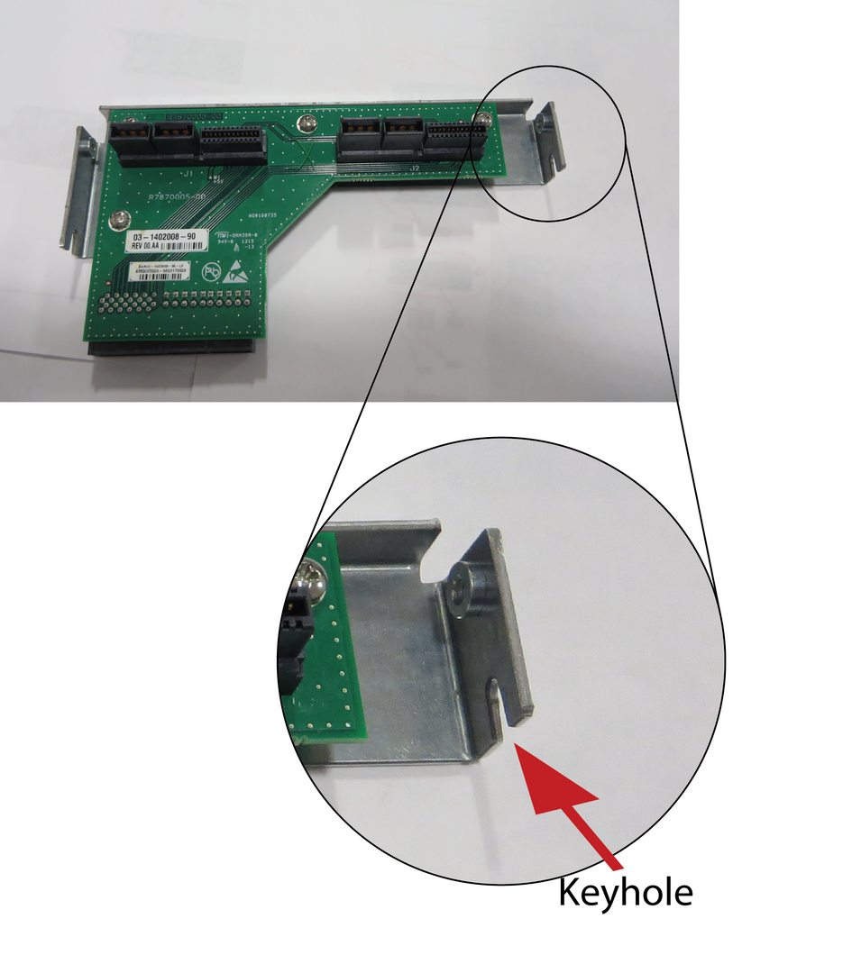
How to install Power Interposer Assembly Install the Power Interposer Assembly and guide onto keyhole features in the sheet metal. Note: Push the Power Interposer Assembly completely inside the connector onto the motherboard. Apply a little pressure until it is fully inserted.Image 15–58 Install the two screws.