This part of the System configuration page lists devices available on the local network and allows adding them to a Linked System Set up.
The Link cards allow for linking multiple Event Master units. Depending on the linking configuration, linked units share inputs, and they expand the number of layers and outputs. For example, beginning with code release 6.0, eight (8) E2 units can be linked as a system.
Just as in section “Configuration Menu > Network resource area”, the unit that is supposed to be added is available in the network resource tab. Any second unit can be added, it only needs to have a separate Unit ID. Change the Unit ID of each system to be different. The default Unit ID is 0 on all E2 chassis models, 1 on all S3 chassis models, and 2 on the EX chassis. On one of the E2s change the Unit ID to 1 from the front panel, or by temporarily adding them as separate systems.
A second E2 or S3–4K unit adds fully double capacity from one unit. There are very few limitations to the capacity and operation is all in all the same as it is for one unit.
Note: After linking chassis, a few menus provide the option of changing between which unit controls you are viewing.
From the Menu bar at the top of all pages, you can select which processor’s details you are viewing, by selecting that processor from the pull down menu.
Note: There is no relationship between Unit ID and Master or Slave selection. Either unit can be Master or Slave in a linked configuration. The only real significance—but totally transparent to users—is the Event Master Toolset communicates only with the Master unit. The Master unit establishes its own connection and handles all communications with the Slave unit(s).
Note: Certain configuration setups are not allowed. These include spanning input or output configurations between an E2 and an S3–4K. If your setup requires this kind of configuration, then you must link together two E2 units or two S3–4K units.
How to Link Two E2 Units
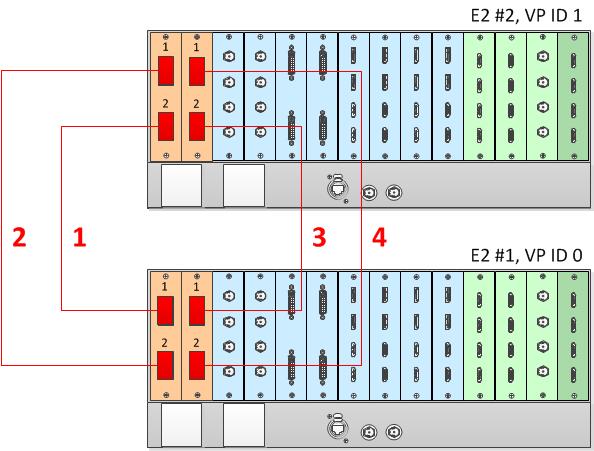
Each E2 comes equipped with two Link cards, always located in slots 1 and 2. Link cards are identified by a yellow stripe at the top. Make sure to use the locking mechanism and then push each cable until it locks in place.
Connect the Link cables provided with each E2 between the Link connectors as follows:
VP ID 0, Link Card slot 1, Link 1 >> VP ID 1, Link Card slot 1, Link 2 [1]
VP ID 0, Link Card slot 1, Link 2 >> VP ID 1, Link Card slot 1, Link 1 [2]
VP ID 0, Link Card slot 2, Link 1 >> VP ID 1, Link Card slot 2, Link 2 [3]
VP ID 0, Link Card slot 2, Link 2 >> VP ID 1, Link Card slot 2, Link 1 [4]
See Image 6–45 for an example of the cabling between two E2 units.
Image 6–45Cabling between two E2 units
Event Master Configuration for Two E2s
Start the Event Master Toolset software.
Make sure that the two E2s are discovered on the network and that they have different Unit IDs.
Drag and drop either of the two E2s in the GUI.
Both E2s will be graphically represented in the Detail View area. The unit which was dropped will show on top of the other unit, which appears grayed out.
You are presented the option to add the bottom, grayed-out unit as a master or as a slave.
Select either add as a master or add as a slave.
(Optional) At this point it is suggested that you select and appropriately name each E2 so that you can identify it in your setup.
How to Link Three E2 Units
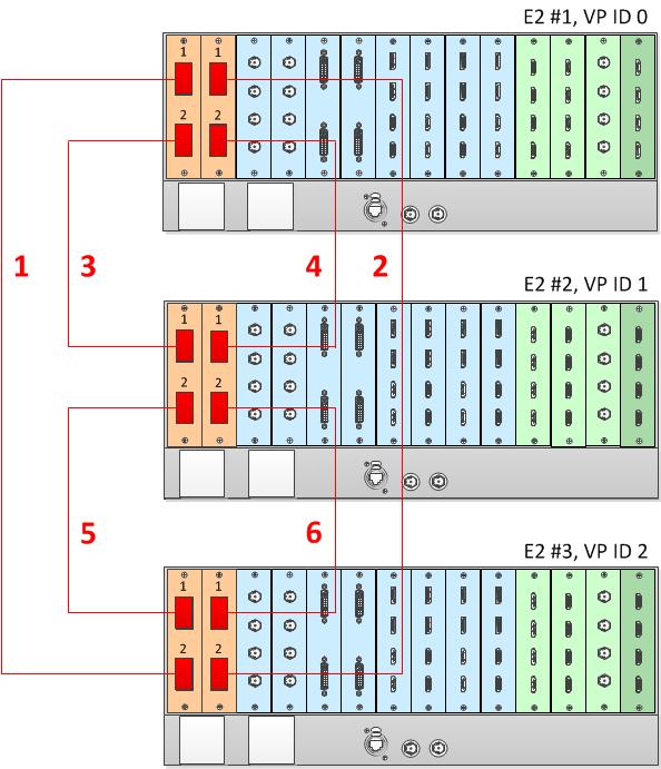
Each E2 comes equipped with two Link cards, always located in slots 1 and 2. Link cards are identified by a yellow stripe at the top. Make sure to use the locking mechanism and then push each cable until it locks in place.
Connect the Link cables provided with each E2 between the Link connectors as follows:
VP ID 0, Link Card slot 1, Link 1 >> VP ID 2, Link Card slot 1, Link 2 [1]
VP ID 0, Link Card slot 2, Link 1 >> VP ID 2, Link Card slot 2, Link 2 [2]
VP ID 0, Link Card slot 1, Link 2 >> VP ID 1, Link Card slot 1, Link 1 [3]
VP ID 0, Link Card slot 2, Link 2 >> VP ID 1, Link Card slot 2, Link 1 [4]
VP ID 1, Link Card slot 1, Link 2 >> VP ID 2, Link Card slot 1, Link 1 [5]
VP ID 1, Link Card slot 2, Link 2 >> VP ID 2, Link Card slot 2, Link 1 [6]
See Image 6–46 for an example of the cabling between three E2 units.
Image 6–46Cabling between three E2 units
Event Master Configuration for Three E2s
Start the Event Master Toolset version 5.1 or higher.
Make sure that the three E2s are discovered on the network and that they have different Unit IDs.
Drag and drop any one of the three E2s in the GUI.
The three linked E2s will be graphically represented in the Detail View area. The unit which was dropped will show on top of the other two units, which appear grayed out.
You will be presented the option to add either of the grayed-out units as a master or as a slave.
Select either add as a master or add as a slave.
Once the system synchronizes the two units that are added to the system, you will be presented the option to add the third unit, at the bottom of the stack in the GUI's Detail View, as the Master or as a Slave.
Select either add as a master or add as a slave.
(Optional) At this point it is suggested that you select and name appropriately each E2 so that you can identify it in your setup.
How to Link an E2 Unit to an EX Unit or to Two Daisy-Chained EX Units
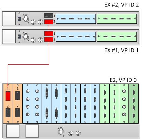
Each E2 comes equipped with two Link cards, always located in slots 1 and 2. Link cards are identified by a yellow stripe at the top. Each EX has two Link sockets. Make sure to use the locking mechanism and then push each cable until it locks in place.
To link an E2 to an EX, connect the Link cables provided with each unit between the Link connectors as follows:
E2 VP ID 0, Link Card slot 1, Link 1 >> EX VP ID 1, Link 2
EX VP ID 1, Link 1 >> EX VP ID 2, Link 2
See Image 6–47 for an example of the cabling between an E2 unit and two EX units.
Image 6–47Cabling between an E2 unit and two daisy-chained EX units
Event Master Configuration for an E2 and an EX
Start the Event Master Toolset software.
Make sure that both the E2 and the EX are discovered on the network and that they have different Unit IDs.
Drop the E2 in the GUI.
If the E2 unit is cabled to an EX unit or a pair of daisy-chained EX units, the EX unit appears as a grayed-out box below the E2 unit in the Diagram area. In the grayed-out EX box a blue button allows you to add the EX to the system as a slave.
Click the blue add button to add the EX unit.
If you are adding two daisy-chained EX units, you must add the first EX in the chain before the second EX in the chain is displayed, then repeat this step to add the second EX in the chain.
(Optional) At this point it is suggested that you select and name appropriately each unit so that you can identify it in your setup.
Note: Each of the four Links on an E2 can be connected to two daisy-chained EX units.
Note: Each of the two link ports on an S3-4K can be linked to two daisy-chained EX units. The procedure is the same as the procedure for linking an E2 to two daisy-chained EX units.
Note: A daisy chain of two EX units cannot have more than two input cards or more than two output cards. Each EX in the chain can have both input cards, both output cards, or an input card and an output card.
How to Link an E2 Unit to an EX Unit with Two VPU Cards
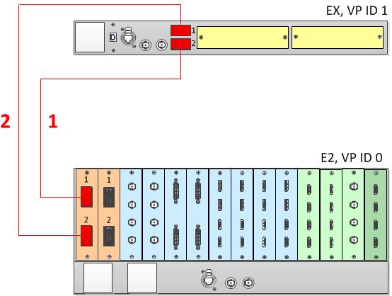
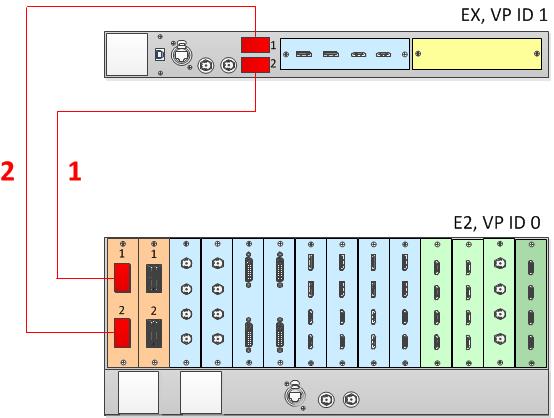
To add up to eight Single or four Mixing Layers to a system, an E2 unit can be linked to an EX unit with two VPU cards. This adds two more VPUs to the system. Each E2 comes equipped with two Link cards, always located in slots 1 and 2. Link cards are identified by a yellow stripe at the top. Each EX has two Link sockets. Make sure to use the locking mechanism and then push each cable until it locks in place.
To link an E2 to an EX, connect the Link cables provided with each unit between the Link connectors as follows:
E2 VP ID 0, Link Card slot 1, Link 1 >> EX VP ID 1, Link 2 [1]
E2 VP ID 0, Link Card slot 1, Link 2 >> EX VP ID 1, Link 1 [2]
See Image 6–48 for an example of the cabling between an E2 unit and an EX unit with two VPU cards.
Image 6–48Cabling between an E2 unit and an EX unit with two VPU cards
How to Link an E2 Unit to an EX Unit with a Mixed I/O/VPU Configuration
To add up to four Single Layers or two Mixing Layers to a system, an E2 unit can be linked to an EX unit with a single VPU card. This adds a another VPU to the system. The VPU can be in either slot 1 or slot 2 on the EX unit, and the other slot may be empty or contain either an Event Master Input card or an Event Master Output card. Each E2 comes equipped with two Link cards, always located in slots 1 and 2. Link cards are identified by a yellow stripe at the top. Each EX has two Link sockets. Make sure to use the locking mechanism and then push each cable until it locks in place.
To link an E2 to an EX, connect the Link cables provided with each unit between the Link connectors as follows:
E2 VP ID 0, Link Card slot 1, Link 1 >> EX VP ID 1, Link 2 [1]
E2 VP ID 0, Link Card slot 1, Link 2 >> EX VP ID 1, Link 1 [2]
See Image 6–49 for an example of the cabling between an E2 unit and an EX unit with a VPU card and either an Event Master Input card or an Event Master Output card.
Image 6–49Cabling between an E2 unit and an EX unit with a VPU card
Note: When an EX unit has VPU cards rather than a combination of Input and Output cards, and it is connected to an E2 processor or to an S3–4K processor, the EX unit an no longer be daisy-chained to another EX unit; both Link connectors on the EX unit must be connected to the E2 or S3–4K Master unit.
Event Master Configuration for Linking an E2 Unit to an EX Unit with VPU Cards
Start the Event Master Toolset version 5.1 or higher.
Make sure that both the E2 and the EX are discovered on the network and that they have different Unit IDs.
Drop the E2 in the GUI.
If the E2 unit is cabled to an EX unit, the EX unit appears as a grayed-out box below the E2 unit in the Diagram area. In the grayed-out EX box a blue button allows you to add the EX to the system as a slave.
Click the blue add button to add the EX unit.
(Optional) At this point it is suggested that you select and name appropriately each unit so that you can identify it in your setup.
How to Link an E2 Unit to Two EX Units, Each with Two VPU Cards
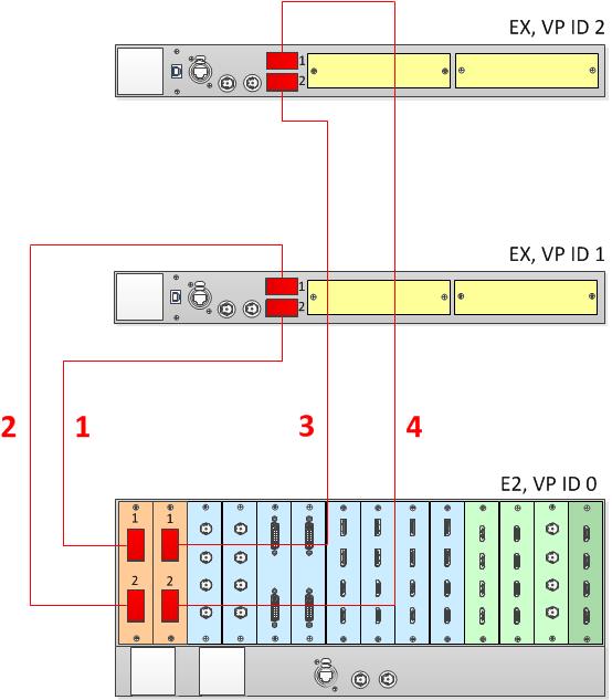
To add up to 16 Single or eight Mixing Layers to a system, an E2 unit can be linked to two EX units, each with two VPU cards. This adds a total of four more VPUs to the system. Each E2 comes equipped with two Link cards, always located in slots 1 and 2. Link cards are identified by a yellow stripe at the top. Each EX has two Link sockets. Make sure to use the locking mechanism and then push each cable until it locks in place.
To link an E2 to two EX units, connect the Link cables provided with each unit between the Link connectors as follows:
E2 VP ID 0, Link Card slot 1, Link 1 >> EX VP ID 1, Link 2 [1]
E2 VP ID 0, Link Card slot 1, Link 2 >> EX VP ID 1, Link 1 [2]
E2 VP ID 0, Link Card slot 2, Link 1 >> EX VP ID 2, Link 2 [3]
E2 VP ID 0, Link Card slot 2, Link 2 >> EX VP ID 2, Link 1 [4]
See Image 6–50 for an example of the cabling between an E2 unit and an EX unit with two VPU cards.
Image 6–50Cabling between an E2 unit and two EX units
Note: When an EX unit has VPU cards rather than a combination of Input and Output cards, and it is connected to an E2 processor or to an S3–4K processor, the EX unit an no longer be daisy-chained to another EX unit; both Link connectors on the EX unit must be connected to the E2 or S3–4K Master unit.
How to Link an E2 Unit to Two EX Units, Each with a Mixed I/O/VPU Configuration
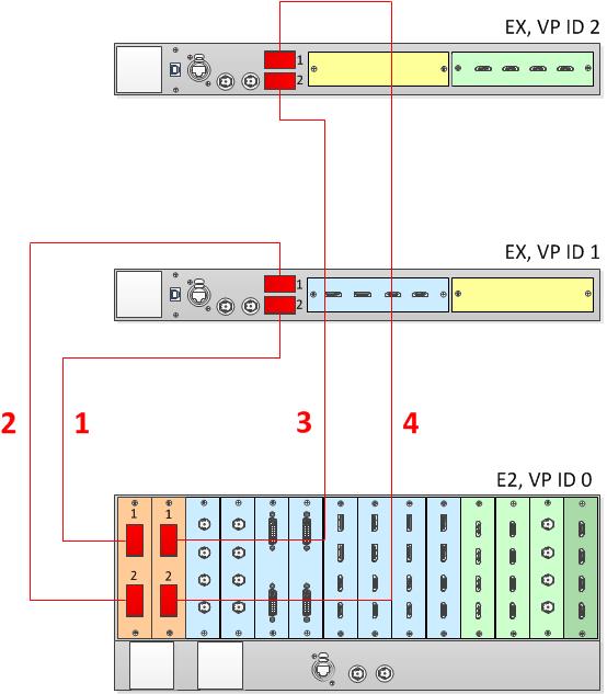
To add up to eight Single Layers or four Mixing Layers to a system, an E2 unit can be linked to two EX units, each with a single VPU card. This adds two VPUs. The VPU can be in either slot 1 or slot 2 on the EX unit, and the other slot may contain either an Event Master Input card or an Event Master Output card. Each E2 comes equipped with two Link cards, always located in slots 1 and 2. Link cards are identified by a yellow stripe at the top. Each EX has two Link sockets. Make sure to use the locking mechanism and then push each cable until it locks in place.
To link an E2 to two EX units, connect the Link cables provided with each unit between the Link connectors as follows:
E2 VP ID 0, Link Card slot 1, Link 1 >> EX VP ID 1, Link 2 [1]
E2 VP ID 0, Link Card slot 1, Link 2 >> EX VP ID 1, Link 1 [2]
E2 VP ID 0, Link Card slot 2, Link 1 >> EX VP ID 2, Link 2 [3]
E2 VP ID 0, Link Card slot 2, Link 2 >> EX VP ID 2, Link 1 [4]
See Image 6–51 for an example of the cabling between an E2 unit and an EX unit with a VPU card and either an Event Master Input card or an Event Master Output card.
Image 6–51Cabling between an E2 unit and two EX units, each with a VPU card
Note: When an EX unit has VPU cards rather than a combination of Input and Output cards, and it is connected to an E2 processor or to an S3–4K processor, the EX unit an no longer be daisy-chained to another EX unit; both Link connectors on the EX unit must be connected to the E2 or S3–4K Master unit.
Event Master Configuration for Linking an E2 Unit to Two EX Units with VPU Cards
Start the Event Master Toolset version 5.1 or higher.
Make sure that both the E2 and the EX are discovered on the network and that they have different Unit IDs.
Drop the E2 in the GUI.
If the E2 unit is cabled to an EX unit, the EX unit appears as a grayed-out box below the E2 unit in the Diagram area. In the grayed-out EX box a blue button allows you to add the EX to the system as a slave.
Click the blue add button to add the EX unit.
(Optional) At this point it is suggested that you select and name appropriately each unit so that you can identify it in your setup.
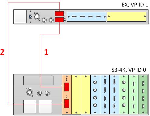
How to Link an E2 Unit and an S3–4K Unit
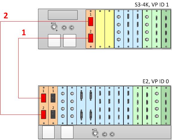
Each E2 comes equipped with two Link cards, always located in slots 1 and 2. Each S3–4K has a single Link card in slot 1. Link cards are identified by a yellow stripe at the top. Make sure to use the locking mechanism and then push each cable until it locks in place.
Connect the Link cables provided with each unit between the Link connectors as follows:
E2 VP ID 0, Link Card slot 1, Link 1 >> S3–4K VP ID 1, Link Card slot 1, Link 2 [1]
E2 VP ID 0, Link Card slot 1, Link 2 >> S3–4K VP ID 1, Link Card slot 1, Link 1 [2]
See Image 6–52 for an example of the cabling between an E2 unit and an S3–4K unit.
Image 6–52Cabling between an E2 unit and an S3-4K unit
Event Master Configuration for Linking an E2 and an S3–4K
Start the Event Master Toolset version 3.2 or higher.
Make sure that both the E2 and the S3–4K are discovered on the network and that they have different Unit IDs.
Drop the E2 in the GUI.
Then drop the S3–4K in the GUI.
The S3–4K will appear grayed-out below the E2.
You will be presented the option to add the S3–4K as a slave. An S3–4K can be added to an E2 only as a Slave.
Select add as a slave.
(Optional) At this point it is suggested that you select and name appropriately each unit so that you can identify it in your setup.
How to Link an E2 Unit and two S3-4K Units
Each E2 comes equipped with two Link cards, always located in slots 1 and 2. Each S3–4K has a single Link card in slot 1. Link cards are identified by a yellow stripe at the top. Make sure to use the locking mechanism and then push each cable until it locks in place.
Connect the Link cables provided with each unit between the Link connectors as follows:
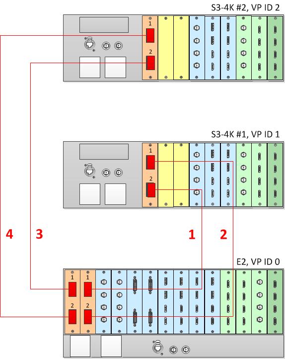
E2 VP ID 0, Link Card slot 2, Link 1 >> S3 VP ID 1, Link Card slot 1, Link 2 [1]
E2 VP ID 0, Link Card slot 2, Link 2 >> S3 VP ID 1, Link Card slot 1, Link 1 [2]
E2 VP ID 0, Link Card slot 1, Link 1 >> S3 VP ID 2, Link Card slot 1, Link 2 [3]
E2 VP ID 0, Link Card slot 1, Link 2 >> S3 VP ID 2, Link Card slot 1, Link 1 [4]
See Image 6–53 for an example of the cabling between an E2 unit and two S3-4K units.
Image 6–53Cabling between an E2 unit and two S3–4K units
Event Master Configuration for Linking an E2 Unit and Two S3-4Ks
Start the Event Master Toolset version 4.2 or higher.
Make sure that the E2 and the S3–4K units are discovered on the network and that they have different Unit IDs.
Drop the E2 in the GUI.
The S3–4K units will appear grayed-out below the E2.
You will be presented the option to add each of the S3–4Ks as a slave. An S3–4K can be added to an E2 only as a slave.
Select either S3–4K and click add as a slave.
Select either add as a master or add as a slave.
When the first S3–4K is done synchronizing with the system, the second S3–4K can then be added to the system.
Select add as a slave.
(Optional) At this point it is suggested that you select and name appropriately each unit so that you can identify it in your setup.
How to Link an E2 Unit, an S3-4K Unit, and four EX Units
Each E2 comes equipped with two Link cards, always located in slots 1 and 2. Each S3–4K has a single Link card in slot 1. Link cards are identified by a yellow stripe at the top. Each EX has two Link sockets. Make sure to use the locking mechanism and then push each cable until it locks in place.
Connect the Link cables provided with each unit between the Link connectors as follows:
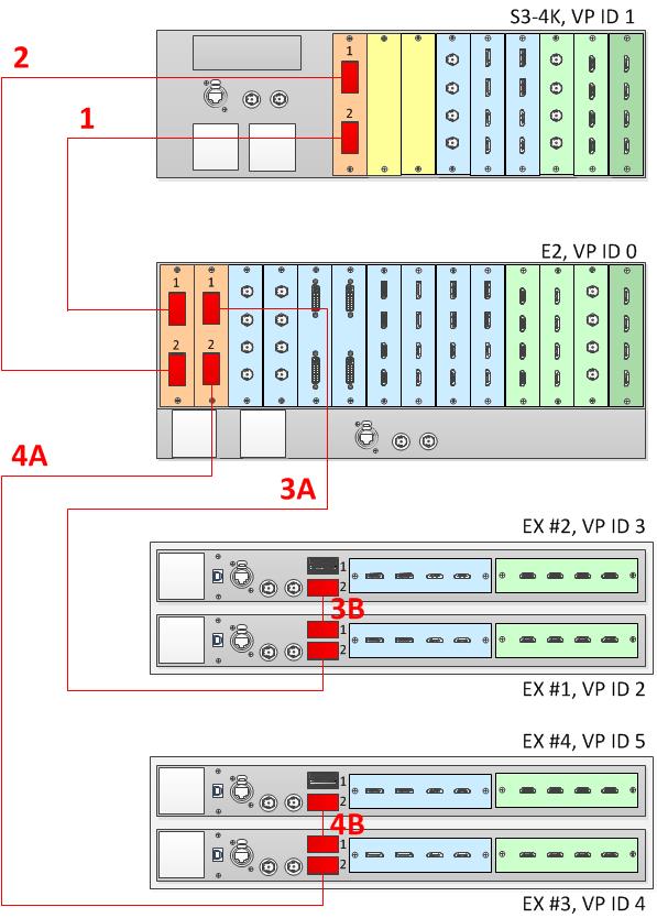
E2 VP ID 0, Link Card slot 1, Link 1 >> S3 VP ID 1, Link Card slot 1, Link 2 [1]
E2 VP ID 0, Link Card slot 1, Link 2 >> S3 VP ID 1, Link Card slot 1, Link 1 [2]
E2 VP ID 0, Link Card slot 2, Link 1 >> EX VP ID 2, Link 2 [3A]
EX VP ID 2, Link 1 >> EX VP ID 3, Link 2 [3B]
E2 VP ID 0, Link Card slot 2, Link 2 >> EX VP ID 4, Link 2 [4A]
EX VP ID 4, Link 1 >> EX VP ID 5, Link 2 [4B]
See Image 6–54 for an example of the cabling between an E2 unit, an S3-4K unit, and four EX units.
Image 6–54Cabling between an E2 unit, an S3–4K unit, and four EX units
Event Master Configuration for Linking an E2, an S3-4K, and four EX Units
Start the Event Master Toolset version 4.1 or higher.
Make sure that the E2, the S3–4K, and the EX units are discovered on the network and that they have different Unit IDs.
Drop the E2 in the GUI.
All linked frames will appear below the E2 as grayed-out representations of each linked frame.
Click the "+Add as Slave" button on the S3–4K.
Once the S3–4K is done synchronizing with the master, you may next add the EX frames as slaves.
Click the blue add button to add the first EX unit.
If the EX is daisy-chained to another EX unit, you must add the first EX in the chain before the second EX in the chain is displayed, then repeat this step to add the second EX in the chain.
Click the blue add button to add the second EX unit.
(Optional) At this point it is suggested that you select and name appropriately each unit so that you can identify it in your setup.
How to Link Three S3–4K Units
Each S3–4K has a single Link card in slot 1, identified by a yellow stripe at the top. Make sure to use the locking mechanism and then push each cable until it locks in place.
Connect the Link cables provided with each S3–4k between the Link connectors as follows:
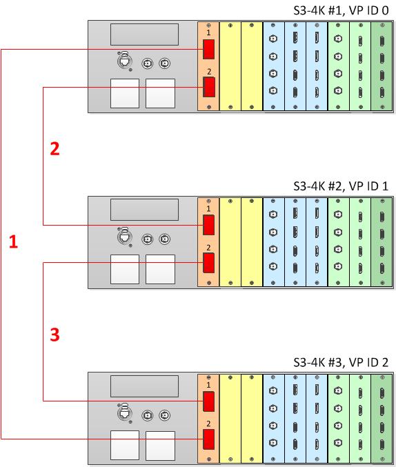
VP ID 0, Link Card slot 1, Link 1 >> VP ID 2, Link Card slot 1, Link 2 [1]
VP ID 0, Link Card slot 1, Link 2 >> VP ID 1, Link Card slot 1, Link 1 [2]
VP ID 1, Link Card slot 1, Link 2 >> VP ID 2, Link Card slot 1, Link 1 [3]
See image 6-39 for an example of the cabling between three S3–4K units.
Image 6–55Cabling between three S3–4K units
Event Master Configuration for Linking Three S3–4Ks
Start the Event Master Toolset version 5.1 or higher.
Make sure that the three S3–4Ks are discovered on the network and that they have different Unit IDs.
Drop one of the S3–4Ks in the GUI.
The other two S3–4Ks will appear below the dropped S3–4K as grayed-out representations of S3–4Ks.
You will be presented the option on each of the two grayed-out units to add as a master or as a slave.
Select either add as a master or add as a slave.
Once the added S3–4K is done synchronizing with the system, the third (grayed-out) S3–4K will be available to add to the system.
You will be presented the option to add the third S3–4K as a master or as a slave.
Select either add as a master or add as a slave.
(Optional) At this point it is suggested that you select and name appropriately each S3–4K so that you can identify it in your setup.
How to Link an S3-4K Unit and an EX Unit with Two VPU Cards
To add up to eight Single or four Mixing Layers to a system, an S3-4K Unit can be linked to an EX Unit with two VPU cards. This adds two additional VPUs to the system. Each S3–4K has a single Link card in slot 1, identified by a yellow stripe at the top. Each EX has two Link sockets. Make sure to use the locking mechanism and then push each cable until it locks in place.
Connect the Link cables provided with each unit between the Link connectors as follows:
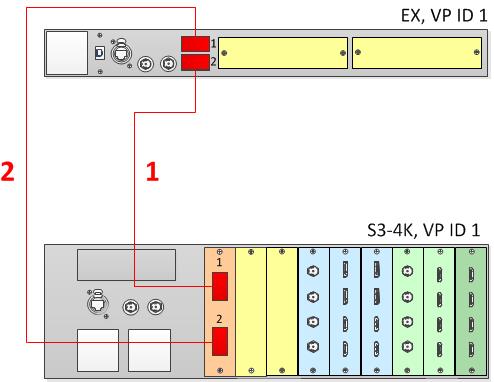
S3 VP ID 0, Link Card slot 1, Link 1 >> EX VP ID 1, Link 2 [1]
S3 VP ID 0, Link Card slot 1, Link 2 >> EX VP ID 1, Link 1 [2]
See Image 6–56 for an example of the cabling between an S3-4K unit and an EX unit with two VPU cards.
Image 6–56Cabling between an S3–4K unit and an EX unit with two VPN cards
Note: When an EX unit has VPU cards rather than a combination of Input and Output cards, and it is connected to an S3–4K processor, the EX unit an no longer be daisy-chained to another EX unit; both Link connectors on the EX unit must be connected to the S3–4K Master unit.
How to Link an S3-4K Unit and an EX Unit with a Mixed I/O/VPU Configuration
To add up to four Single or two Mixing Layers to a system, an S3-4K Unit can be linked to an EX Unit with a single VPU card. This adds another VPU to the system. The VPU can be in either slot 1 or slot 2 on the EX unit, and the other slot may be empty or contain either an Event Master Input card or an Event Master Output card. Each S3–4K has a single Link card in slot 1, identified by a yellow stripe at the top. Each EX has two Link sockets. Make sure to use the locking mechanism and then push each cable until it locks in place.
Connect the Link cables provided with each unit between the Link connectors as follows:
S3 VP ID 0, Link Card slot 1, Link 1 >> EX VP ID 1, Link 2 [1]
S3 VP ID 0, Link Card slot 1, Link 2 >> EX VP ID 1, Link 1 [2]
See Image 6–57 for an example of the cabling between an S3-4K unit and an EX unit with two VPU cards.
Image 6–57Cabling between an S3–4K unit and an EX unit with a single VPN card
Note: When an EX unit has VPU cards rather than a combination of Input and Output cards, and it is connected to an S3–4K processor, the EX unit an no longer be daisy-chained to another EX unit; both Link connectors on the EX unit must be connected to the S3–4K Master unit.
Event Master Configuration for Linking an S3-4K Unit and an EX Unit with VPU Cards
Start the Event Master Toolset version 5.1 or higher.
Make sure that both the S3–4K and the EX units are discovered on the network and that they have different Unit IDs.
Drop the S3–4K in the GUI.
If the S3–4K unit is cabled to the EX unit, the EX unit appears as a grayed-out box below the S3–4K unit in the Diagram area. In the grayed-out EX box a blue button allows you to add the EX to the system as a slave.
Click the blue add button to add the EX unit.
(Optional) At this point it is suggested that you select and name appropriately each unit so that you can identify it in your setup.
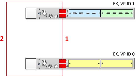
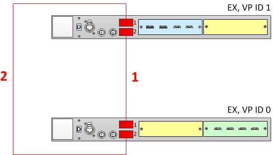
How to Link Two EX Units with VPU Cards
To create a system comprising two VPU cards, an Input card, and an Output card, two EX units can be linked together. The system must have two VPU cards; both VPU cards can be on one EX unit, or each EX unit can have a single VPU card and either an Input card or an Output card. Such a system provides four Inputs, four Outputs, four Mixing Layers, and no MVR outputs. Each EX has two Link sockets. Make sure to use the locking mechanism and then push each cable until it locks in place.
Connect the Link cables provided with each unit between the Link connectors as follows:
EX VP ID 0, Link 1 >> EX VP ID 1, Link 2 [1]
EX VP ID 0, Link 2 >> EX VP ID 1, Link 1 [2]
See Image 6–58 and Image 6–59 for examples of the cabling between two EX units with VPU cards.
Image 6–58Cabling between an EX unit with Input and Output cards and an EX unit with a two VPU cardsImage 6–59Cabling between an EX unit with an Input and a VPU card and an EX unit with a VPU and an Output card
Event Master Configuration for Linking Two EX Units with VPU Cards
Start the Event Master Toolset version 5.1 or higher.
Make sure that both the EX units are discovered on the network and that they have different Unit IDs.
Drop the first EX in the GUI.
If the EX unit is cabled to a second EX unit, the second EX unit appears as a grayed-out box below the first EX unit in the Diagram area. In the grayed-out EX box a blue button allows you to add the EX to the system as a slave.
Click the blue add button to add the second EX unit.
(Optional) At this point it is suggested that you select and name appropriately each unit so that you can identify it in your setup.
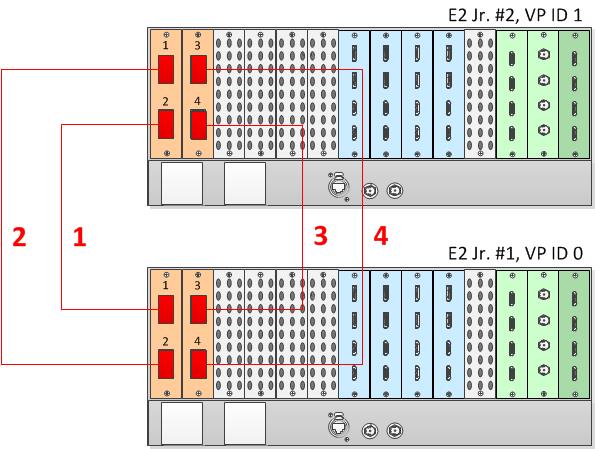
Other Linking Configurations: E2 Jr. and S3–4K Jr.
E2 Jr. and the S3–4K Jr. units do not ship with Link cards, but they support linking as an upgrade option. To support linking with an E2 Jr. or an S3–4K Jr. unit, you may purchase an Event Master Link card and install it in Slot #1 of the unit. You may also need to purchase additional Event Master Link cables.
Note: When linking two E2 Jr. units, the user must buy two Link cards per unit and link the two E2 Jr. units as two E2 units would be linked. A single Link card per unit is required to link an E2 Jr. with an S3–4K Jr. or to link an S3–4K Jr. to another S3–4K Jr.
To link an E2 Jr. unit to another E2 Jr. unit, connect Link cables between the Link connectors as follows:
VP ID 0, Link Card slot 1, Link 1 >> VP ID 1, Link Card slot 1, Link 2 [1]
VP ID 0, Link Card slot 1, Link 2 >> VP ID 1, Link Card slot 1, Link 1 [2]
VP ID 0, Link Card slot 2, Link 1 >> VP ID 1, Link Card slot 2, Link 2 [3]
VP ID 0, Link Card slot 2, Link 2 >> VP ID 1, Link Card slot 2, Link 1 [4]
See Image 6–60 for an example of the cabling between two E2 Jr. units.
Image 6–60Cabling between two E2 Jr. units
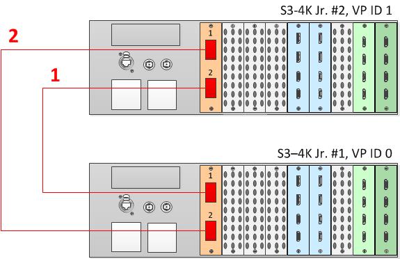
To link an S3–4K Jr. unit to another S3–4K Jr. unit, connect Link cables between the Link connectors as follows:
VP ID 0, Link Card slot 1, Link 1 >> VP ID 1, Link Card slot 1, Link 2 [1]
VP ID 0, Link Card slot 1, Link 2 >> VP ID 1, Link Card slot 1, Link 1 [2]
See Image 6–61 for an example of the cabling between two S3–4K Jr. units.
Image 6–61Cabling between two S3–4K Jr. units
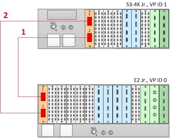
To link an E2 Jr. unit to an S3–4K Jr. unit, connect Link cables between the Link connectors as follows:
VP ID 0, Link Card slot 1, Link 1 >> VP ID 1, Link Card slot 1, Link 2 [1]
VP ID 0, Link Card slot 1, Link 2 >> VP ID 1, Link Card slot 1, Link 1 [2]
See Image 6–62 for an example of the cabling between an E2 Jr. unit and an S3–4K unit.
Image 6–62Cabling between an E2 Jr. unit and an S3–4K Jr. unit
Event Master Configuration
Start the Event Master Toolset version 4.1 or higher.
Make sure that both units are discovered on the network and that they have different Unit IDs.
Drop the first in the GUI.
Drop the second unit in the GUI.
You will be presented the option to add as a new system, add as a master, or add as a slave. An S3–4K can be added as a Master or Slave to an E2.
Add the second unit as a slave.
(Optional) At this point it is suggested that you select and name appropriately each unit so that you can identify it in your setup.
Connection Control
From the configuration page switch from the detail view to the System view and ensure that the status is good (green) for all link connections. If any connections is shown as red, please check that the cables were connected as described in step b and they were fully seated.
Programming
Referring to section “System Setup”, you may now proceed with the configuration and programming of the E2 linked system having full access to all resources in the system.
Auto Creation
If you choose to auto create your inputs, outputs and MVR outputs they will be created from Unit ID 0 first and then followed by the ones from Unit ID 1.
Configuration Order
You may proceed with defining your destinations, auxes and assign your layers. It is recommended that you setup all screen destinations and make layer assignment before you setup the Multiviewer(s).
Note: The Multiviewer and Web App sections of the Event Master Toolset have an additional selection. You may select whether you are viewing the Master or Slave E2 Multiviewer windows or the Master or Slave E2 Web App. The selection names correspond to the way you named the units in steps above.
Backup and Restore
When backing up and restoring your system you only need to backup and restore from the Master Unit.
Genlock
When genlocking your system to an external sync you only need to bring the signal into the Master unit and select lock to External from the Event Master Toolset.
A note about Multiviewer and Linked Systems
In an E2 linked setup as you create destinations and assign layers the Event Master Toolset determines the best resource allocation for your configuration.
In order to make optimal use of expansion links, screens in linked E2 systems must be viewed on the Multiviewer in the E2 where the Event Master Toolset has allocated it.
Optimal allocation may cause a screen allocation to move from one E2 to another as screen resources are changed.
This may result in a screen already placed in a Multiviewer to not be operative. The Event Master Toolset will change the UMD text to “Screen not viewable on this MVR”.
All you need to do is delete the screen from the Multiviewer displaying this message and place it on the other Multiviewer.
A note about Backgrounds
Multi-connector Background sources with more input links than can be used by the VPUs of one unit, should still be configured on only one unit and not split up among the multiple chassis in a system.
More information
For more information on how to prevent cable and connector damage on the Link Cards for E2 and S3–4K, see “InfoT-1294: Cable and Connector Damage on the Link Cards for E2 Series and S3–4K Series Presentation Switchers”.
For more information on Event Master Link-Cable solutions, see “InfoT-1301: Event Master Link-Cable Solutions for E2, S3–4K, and EX”
Tip: Always check for updated information that may have come out since this manual was published and for the latest version of all documents on https://www.barco.com.