Flow chart


Several items must be removed from the chassis, before the motherboard may be removed. These items fall into two groups: rear-panel elements and chassis elements. Once these items have been removed, you may remove the motherboard.
| Event Master Series card |
| BNC Hex Nuts (x2) |
| BNC Toothed Washers (x2) |
| BNC Insulating Bushing (x1) |
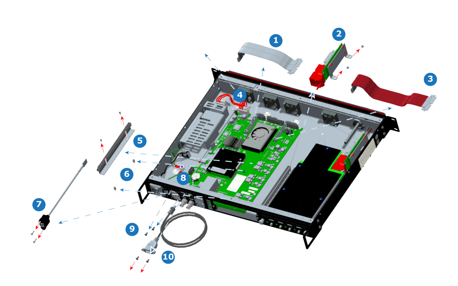
| Slot #1 Edge-card Ribbon Cable |
| EX Interposer (Slot #1) |
| Slot #2 Edge-card Ribbon Cable |
| DC Power Cable |
| Edge-card Guide |
| USB Type B Cable |
| DisplayPort Cable |
| EX Motherboard |
| Fansink |
Any Event Master series card fits Slot #1 and Slot #2.
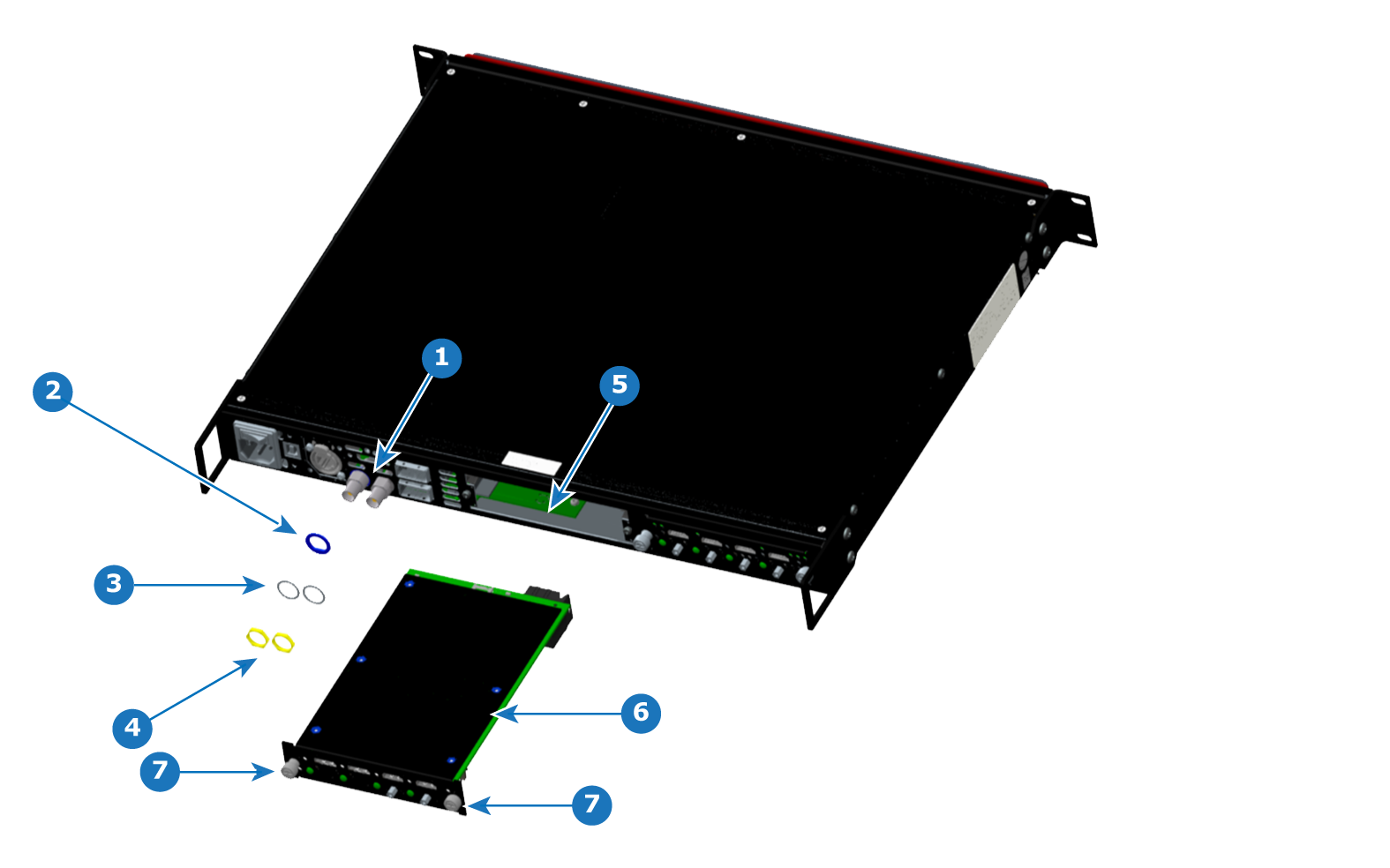
Remove the hex nuts and the toothed washers from both Genlock BNC connectors, and remove the insulating bushing from the Genlock In BNC connector.
Note: Do not forget to install the insulating bushing on the Genlock In BNC connector during re-installation.
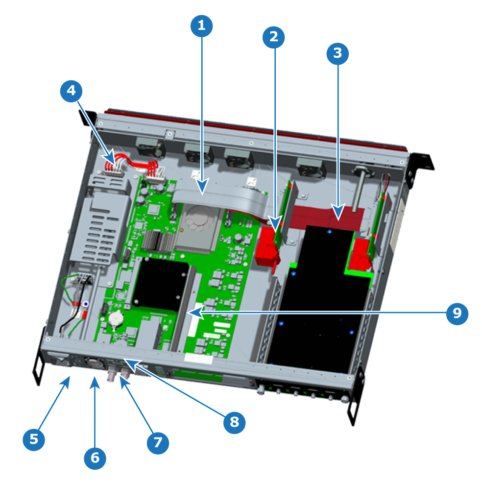
Snip the zip ties on the rear USB cable and the DisplayPort connector cable.
CAUTION: Not snipping the zip ties around the cables to be moved or removed may result in damage to the zip-tie mounts and the surfaces to which they are attached.
Remove the two screws that fasten the Slot #1 interposer to the floor of the chassis, and remove the interposer from the chassis.
These are located on the bottom of the chassis near the front and close to the center of the chassis when looking from left to right.
Remove the two screws that fasten the RJ45 (Ethernet) mounting plate to the rear panel of the chassis.
These screws are below and to the left, and above and to the right of the RJ45 mounting plate. Do not remove the screws on the mounting plate itself. The mounting plate should remain attached to the RJ45 connector on the motherboard.
Unscrew and remove the card-guide standoffs from the chassis.
These go through slots in the motherboard, but the motherboard cannot be removed without first removing the standoffs.
The chassis elements are shown removed from the chassis in Image 16–19.
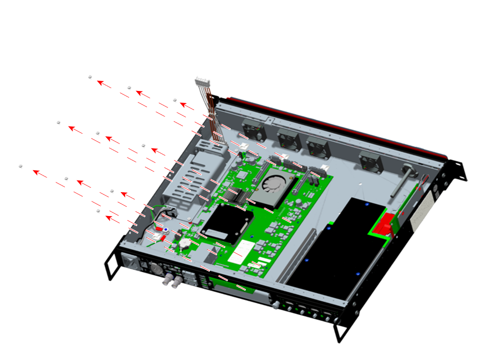
Lift the front end of the motherboard, and rotate the motherboard up.
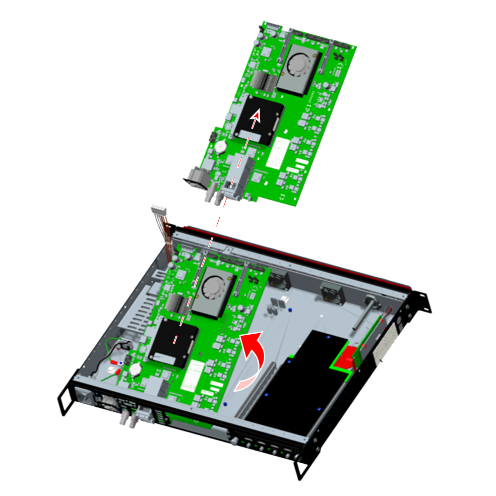
Remove the motherboard from the chassis.
Note: There is one BNC insulator on the Genlock input connector. Make sure you put this to the side, so you can re-install it when re-installing the motherboard.
To install the motherboard in the EX chassis, follow the steps of the removal procedure in reverse order.
Install the rear-panel elements.
Note: Do not forget to install the insulating bushing on the Genlock In BNC connector—both internal to the chassis and external—before installing the toothed washers and hex nuts.