
14.23 Genlock Assembly

Flow chart
Image 14–71
Overview
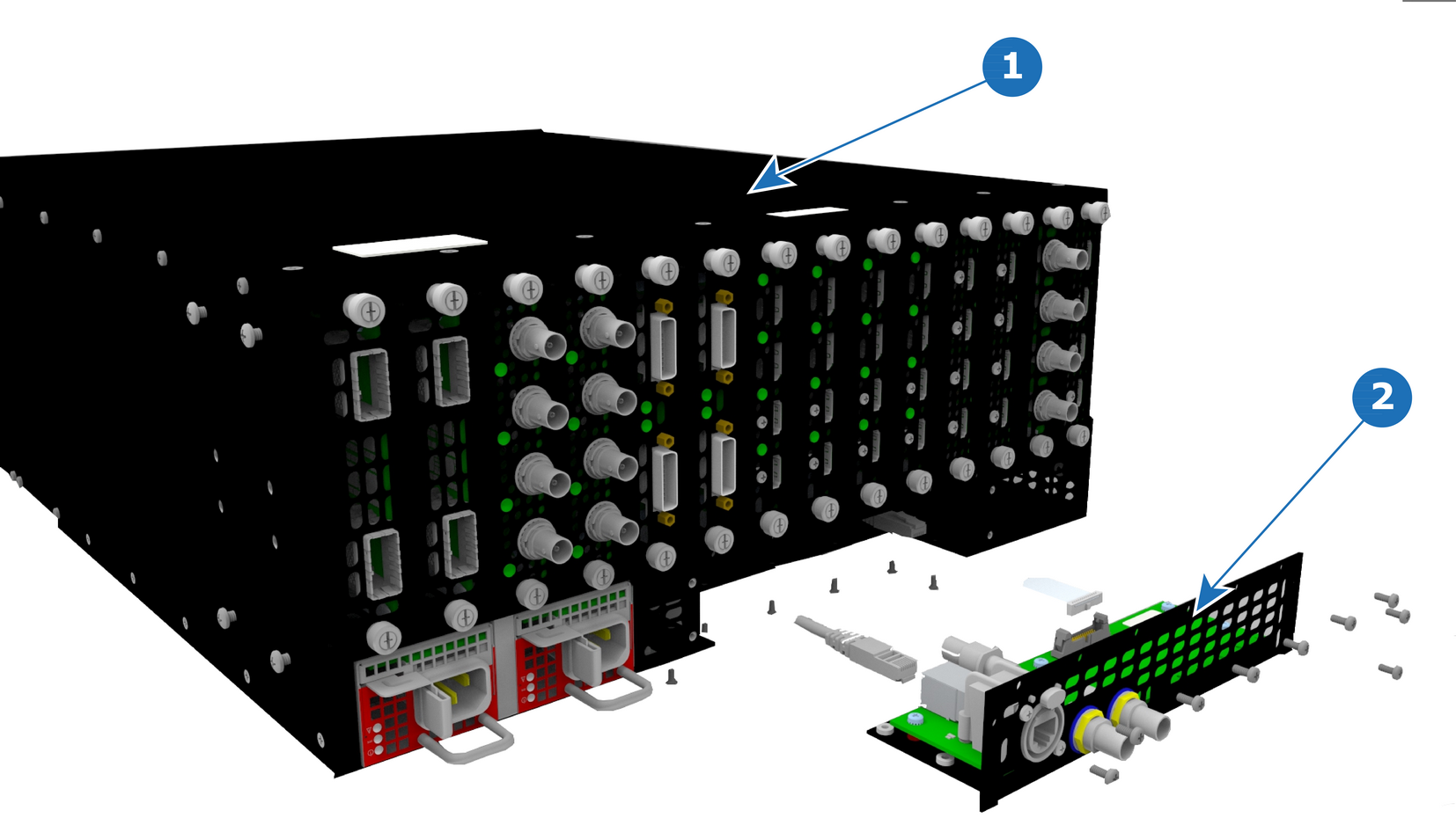
Image 14–72 E2 Gen 1 genlock assembly
1
Chassis
2
Genlock assembly
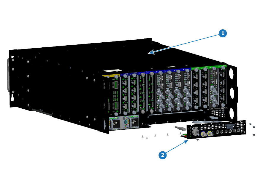
Image 14–73 E2 Gen 2 genlock assembly
1
Chassis
2
Genlock assembly
Concerned parts
Genlock Assembly
Necessary tools

1 x Phillips Screwdriver #2

How to remove the Genlock Assembly
  1. Remove the seven flat head screws (4-40 X .25) that attach the Genlock assembly to the rear side of the chassis.
  2. Remove the ten pan head screws (4-40 X .25) that attach the Genlock assembly to the rear of the chassis.
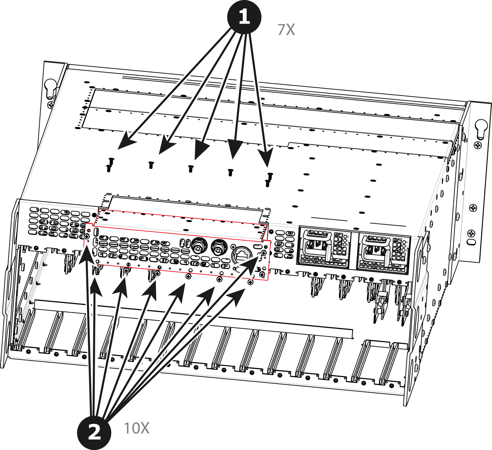
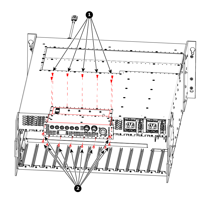
    Image 14–74 E2 Gen 1 – Genlock assembly removal
    1
    Flat-head, 4-40 X .25 screws (x7)
    2
    Pan-head, 4-40 X .25 screws (x10)
    Image 14–75 E2 Gen 2 – Genlock assembly removal
    1
    Flat-head, 4-40 X .25 screws (x7)
    2
    Pan-head, 4-40 X .25 screws (x10)
  3. Gently pull the Genlock assembly away from the unit . Don't pull the assembly too far back because there are still 2 cables attached.

    Note: At this point there are still 2 cables connecting the Genlock Assembly to the unit.
  4. Unlatch the VFD ribbon cable from the connector and pull it up and away from the Genlock board.
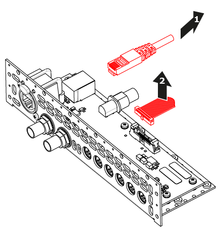
    Note: This cable connects the Genlock board to the System-Power board.
    Image 14–76 E2 Gen 1 – Genlock assembly cables
    1
    Ethernet cable
    2
    VFD ribbon cable
  5. Unlatch the Ethernet cable from the connector and pull back and away from the Genlock board.

    Note: This cable connects the Genlock board to the System-Power board.
  6. (E2 Gen 2 only) Remove the DisplayPort-cable screws, then remove the DisplayPort cable
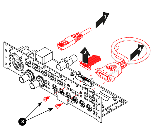
    Image 14–77 E2 Gen 2 – Genlock assembly cables
    1
    Ethernet cable
    2
    VFD ribbon cable
    3
    DisplayPort cable screws
    4
    DisplayPort cable
How to install the Genlock Assembly

To install the Genlock Assembly follow the same procedure in the reverse order.