Flow chart


| Tri-Combo Input |
| Tri-Combo Output |
| Fansink kit |
Phillips screwdriver PH2
The procedure for disassembling a TCI card is the same as that for disassembling a TCO card. The images accompanying these procedures show the TCI card, but the procedures apply to both cards.
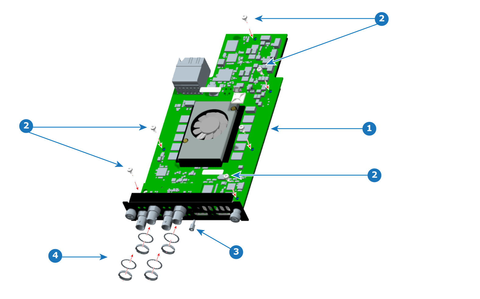
Cut the zip tie that secures the fan cable, and remove the fan cable.
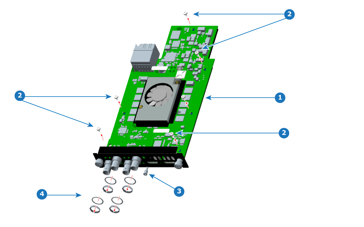
Loosen and remove the standoff.
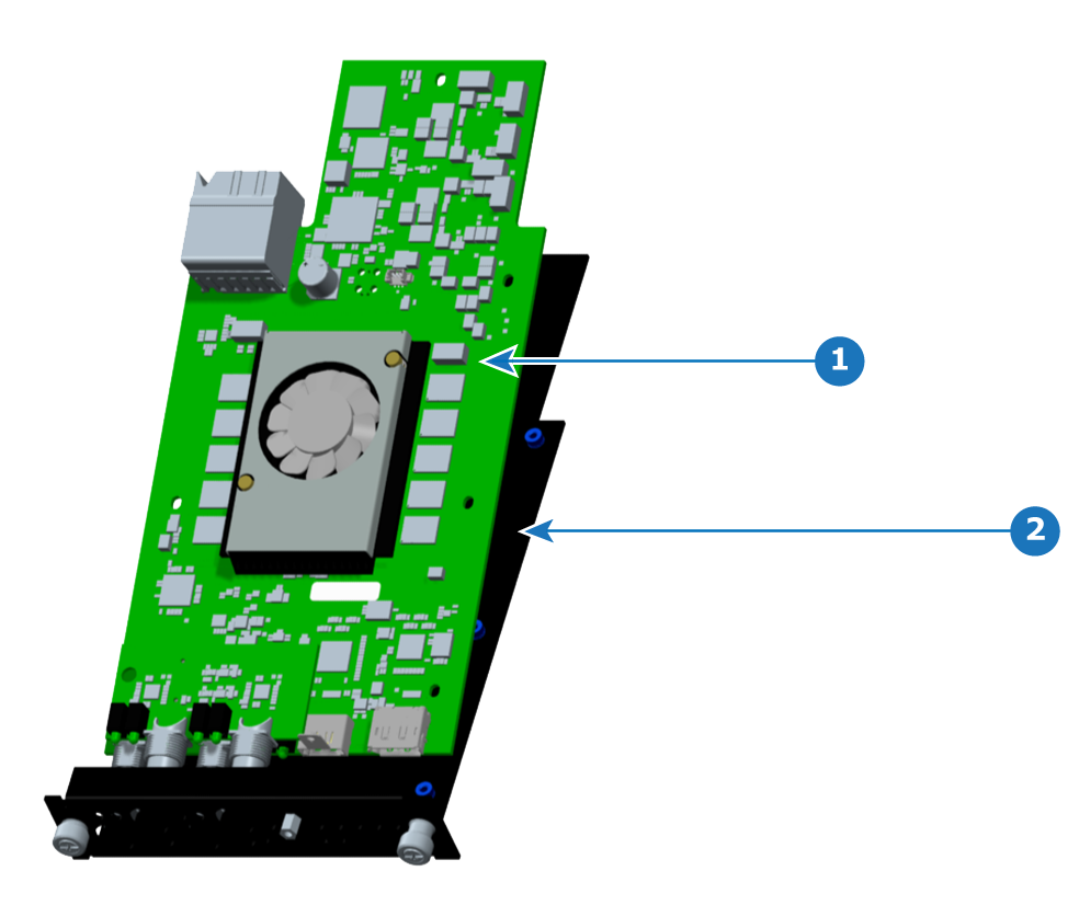
Remove the PCBA from the sheet metal bracket.
Remove the fansink (heatsink fan), if necessary.
Turn over the PCBA and push the fansink pins. (The fansink pins will not come free of the fansink.)
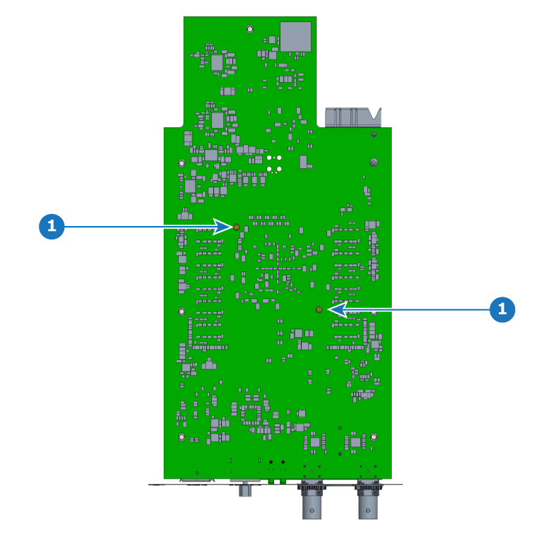

The procedure for assembling a TCI card is the same as that for assembling a TCO card. The images accompanying these procedures show the TCI card, but the procedures apply to both cards.
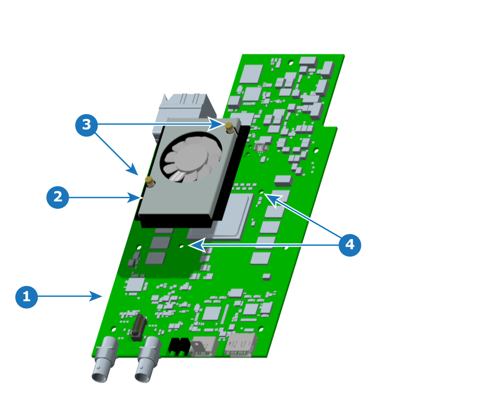
Install the fansink (heatsink fan) on the main board (PCBA), if the fansink is not already present.
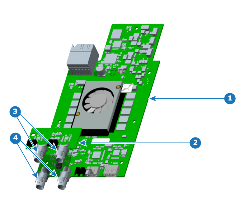
Place kapton tape on the rear portion of the mainboard BNC connectors.
(Kapton tape is not needed on the mezzanine BNC connectors.)
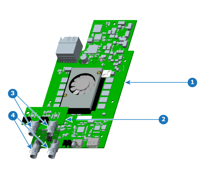
Install the mezzanine on the PCBA.
On the TCI card, make sure that the LED's length is a maximum of 1.2 mm below the bottom surface of the PCBA.
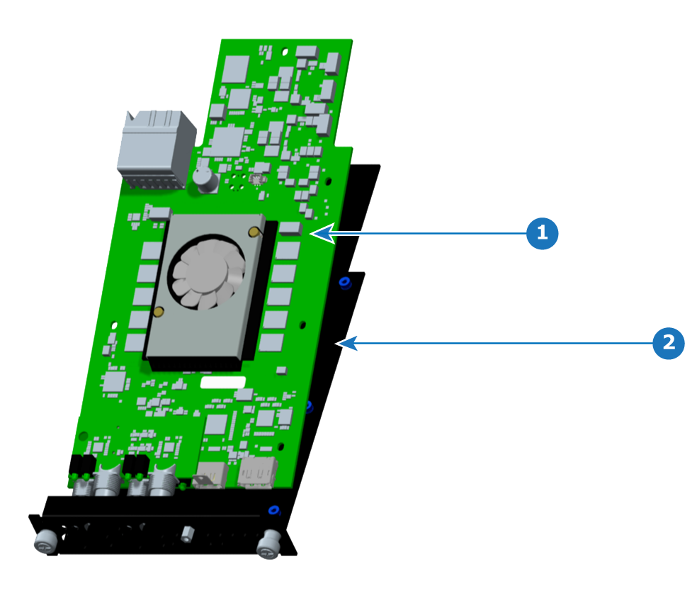
Place the PCBA on the sheet metal bracket, aligning the screw holes of the PCBA with the screw holes of the bracket.