7.16 Configuration Menu > Add Aux Destinations

General

In this procedure, you will Add Aux Destinations from the defined outputs.

Prerequisite
Note: If more than one Aux Destination is utilized, repeat the below steps until all Destinations are added.
Add Aux Destinations
  1. From the diagram area click on the output that you want to use for the auxiliary destination.
  2. Click on the Destination tab to define auxiliary destinations for the configured outputs.
  3. Click on the +Add Aux Destination blue button to assign the output to the Aux destination.
  4. When the destination is created a green rectangle appears next to the EMP diagram.
(Optional) Edit the Name
  1. Double click on “Destination1” in the Name list to edit the name.
  2. When the area turns blue, click the eraser icon to clear the field.
  3. Type a new name and hit enter when done.
(Optional) Adjust Destination Parameters

Click on the “Adjust” tab that is located on the top. In this Tab there are three sub tabs: Assign, Output and Wide (See below).

(Optional) Adjust Destination Parameters part 1 > Assign Tab

From this menu you can:

  1. Edit the name.
  2. Delete outputs (remove the output assignment from the Aux destination).
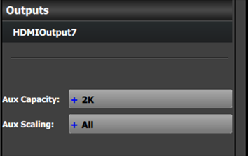
  3. Select the Auxiliary Capacity:

    Aux Capacity defines how much resolution, or actual LINKs of data can be input into the scaler. The default setting is "2K" or single link, which refers to the limit of how much signal bandwidth can be input into the auxiliary scaler. The other three choices are: DL (Dual Link), 4K (four links worth of signal bandwidth) and 8L (eight links worth of signal bandwidth). 8L refers to eight Links of 2K data.

    Each of the settings will allow for different size input / still and destination sources from the Input Resource tab covered in the Programming Section below.

    Some examples of the scaling capacity limitations include:

    • 2K = Up to 2048×1080p60 or WUXGA (1920×1200p60)
    • DL = Up to 2560×1600p60 or 3840×1200p60
    • 4K = UHD (3840×2160p60), 4K-DCI (4096×2160p60) or 7680×1200p60
    • 8L = 8192×2160p60 or 16384x1080p60.

    These examples are capable for backgrounds and screen destinations.

  4. Select the Aux Scaling:

    Aux Scaling defines how the input image is scaled/displayed inside the auxiliary destination. The default setting is "All." The other two choices are "Center Cut" or "Custom."

    • All scales the entire image to fit within the horizontal and vertical resolution of the Aux destination's output. If the image has an aspect ratio that differs from that of the Aux destination, the image will appear either letter-boxed (black bars at the top and bottom of the image) or pillar-boxed (black bars at the left and right of the image).
    • Center Cut, if the input image aspect ratio differs from that of the Aux destination, scales the center portion of that image to fit within the horizontal and vertical resolution of the destination's output. If the input image has the same aspect ratio as the Aux destination, the entire image is scaled to fit the vertical and horizontal resolution of the destination, showing the entire image.
    • Custom scales the input image as if it is inside a "single" (non-mixing) layer. The window size and position, source size (zoom), and edge masking of the image can all be adjusted in this mode.
(Optional) Adjust Destination Parameters part 2 > Output Tab

From this menu you can:

  1. See the output canvas (raster) size used for the Aux.
  2. Choose more actions in sub tabs:

    • Position:

      • Enable Test Patterns with raster box and enable diagonal motion
      • Define the Area of interest (AOI).
    • Color:

      • Perform color adjustments.
    • Timing:

      • Read the timing parameters associated with the selected format.
    • Connector Settings:

      • Select SDI type and SMPTE standards.
      • Select Color/Sample/Bit, Color Space, Colorimetry, and Gamma Fx settings.
      • Turn HDCP mode On/Off (not applicable for SDI).
      • Adjust the Connector Mapping from Horizontal to Vertical or Grid.
(Optional) Adjust Destination Parameters part 3 > Wide Tab

No wide-screen adjustments are available for Aux Destinations.

(Optional) Delete Destinations
  1. Click on the blue button Delete Destination(s).
  2. From the Name list click on the “x” space next to the output(s) you wish to delete. Or select the box to the right of the EMP representation in the workspace.
  3. Hit the red button. All of the selected Destination(s) will be removed from the list.