15.34 Ethernet Cable

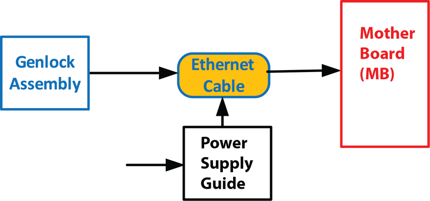
Flow chart
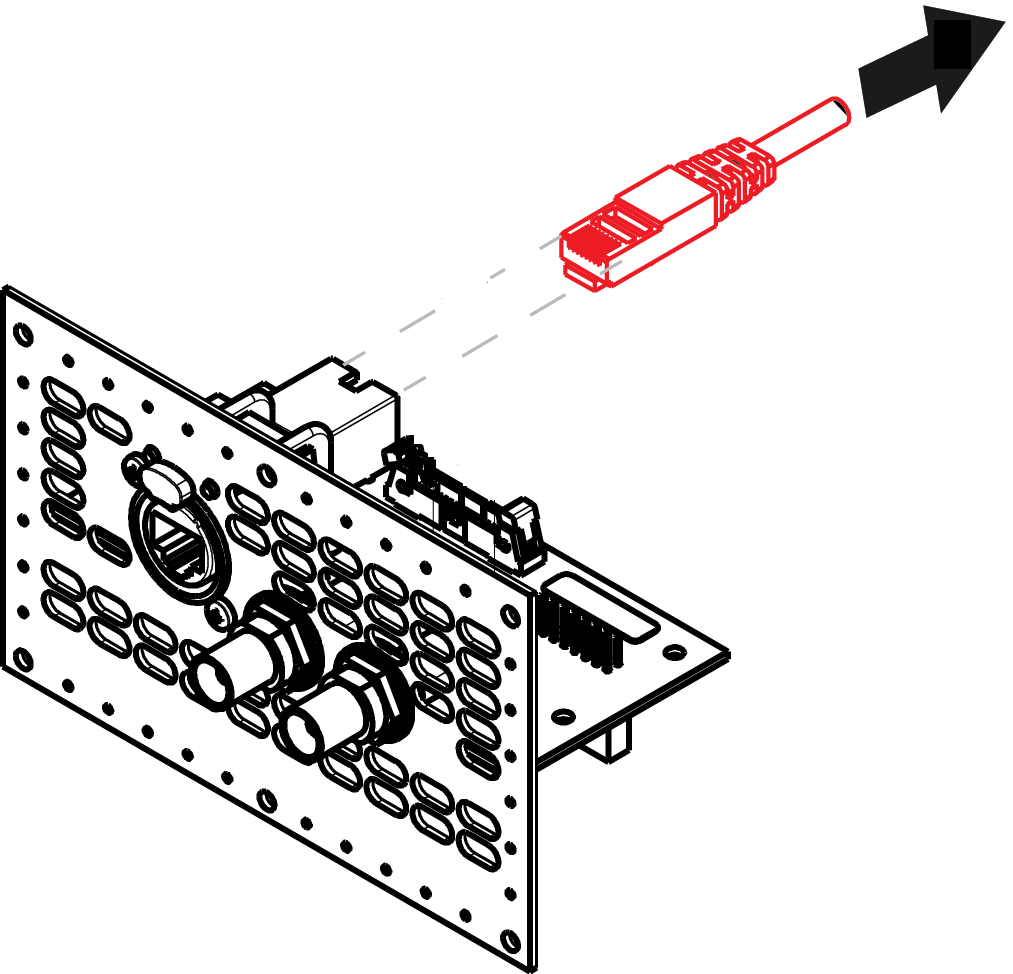
Image 15–96
Note: The Ethernet cable connects the Genlock board to the Motherboard. This procedure provides instructions on how to remove the cable from both sides.
Note: This procedure requires to remove the Power supply Guide to unplug the cable from the motherboard.
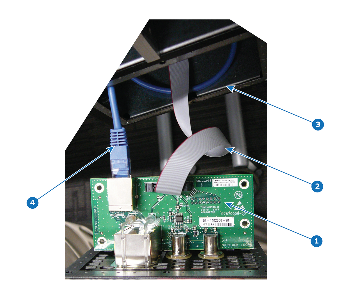
Overview
Image 15–97
1
Genlock card
2
Genlock cable
3
Chassis
4
Ethernet cable
Concerned parts
S3 Cable Kit Set
Necessary tools

1 x Phillips Screwdriver #2

How to remove the Ethernet cable
  1. Remove the Genlock assembly and pull it away to expose the cables behind it (refer to the related procedure).
  2. Locate the Ethernet connector on the Genlock assembly and push the locking clip on the Ethernet cable so it can be released from the socket.

    Image 15–98
    Note: From this step, only the other end of the Ethernet cable stays connected to the motherboard. Unfortunately it is necessary to remove the Power supply Guide to unplug it. (refer to the “Process Overview”).
  3. Follow the steps detailed in other procedures to remove Power supply Guide.
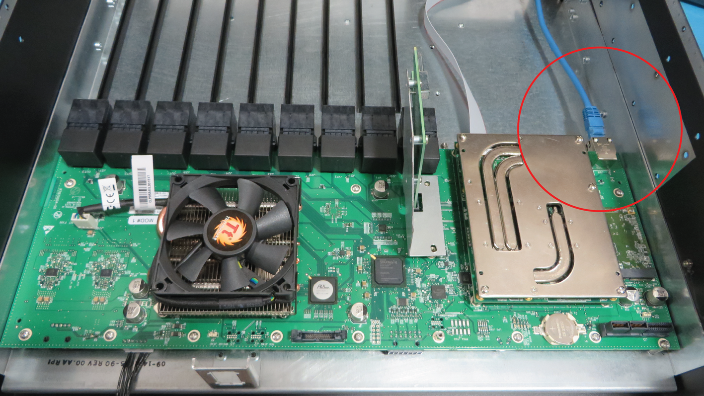
  4. Locate the Ethernet cable that is plugged on the Motherboard and push the locking clip on the Ethernet cable so it can be released from the socket.

    Image 15–99
  5. Pull the cable out of the unit .
How to install the Ethernet Cable

To install the Ethernet Cable follow the same procedure in the reverse order.