General
Output configurations that are created in the previous menus are assigned to destination in the Destination Panel.

Output configurations that are created in the previous menus are assigned to destination in the Destination Panel.
Destination configuration menu is accessed by clicking on the Destination tab.
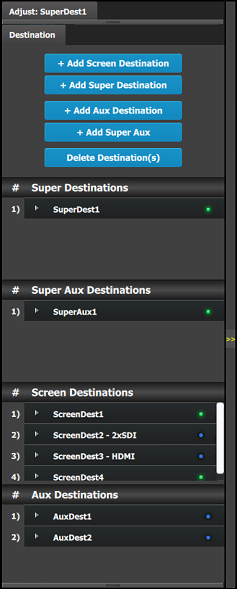 | This menu provides:
|
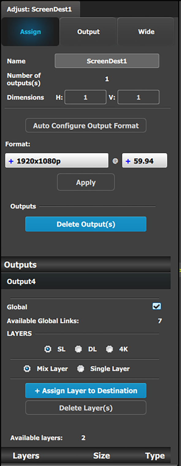
Note: Users can now link more than two E2s, or more than two S3–4Ks in a single system. In this configuration, only input expansion is supported. Users can select up to 48 SL inputs for linked E2 systems and 24 SL inputs for linked S3–4K systems to be marked it as a "Global Input." Global Input checkboxes are available in the Configuration page, under the Input and Background tabs for inputs. Because Screen Destinations can be inputs to Layers and AUX Destinations, Screen Destinations can also be designated as "Global Inputs." The Destination tab in the Configuration page tracks the number of available global links. To designate a Screen Destination as a global input, check the "Global" checkbox on the Adjust panel for the Screen Destination.
|  |
A few words about destination formats:
For Super Destinations: Super Destinations do not have an output format. As Screen Destinations are added to a Super Destination, the pixels from the Screen Destinations are added together to create the canvas size of the Super Destination.
Screen Destinations of different resolutions can be combined into a Super destination.
The placement of the individual Screen Destinations need not be edge-to-edge. Screen Destinations can be placed in arbitrary positions, creating a new pixel coordination system and allowing manipulation of Super Layers within that new system.
For Super AUX Destinations: Super AUX Destinations work with AUX Destinations as AUX Destinations work with Output configurations. Create a Super AUX, and drag and drop the desired AUX Destinations into it. Use the H/V Offset edit boxes to adjust the layout relationship of the AUX destinations that are assigned to the Super AUX.
The following rules apply when defining a Screen / AUX Destination configuration:
Destinations accept only the same Output connector types.
Different connector formats cannot be mixed in the same destination.
Destinations accept Output configurations only with the same number of Output connectors.
Output configurations with a different number of connectors cannot be combined. For example if the first Output configuration added is an HDMI output configuration with two (2) connectors (grouped connector), an HDMI output configuration with one (1) connector cannot be added to the same destination.
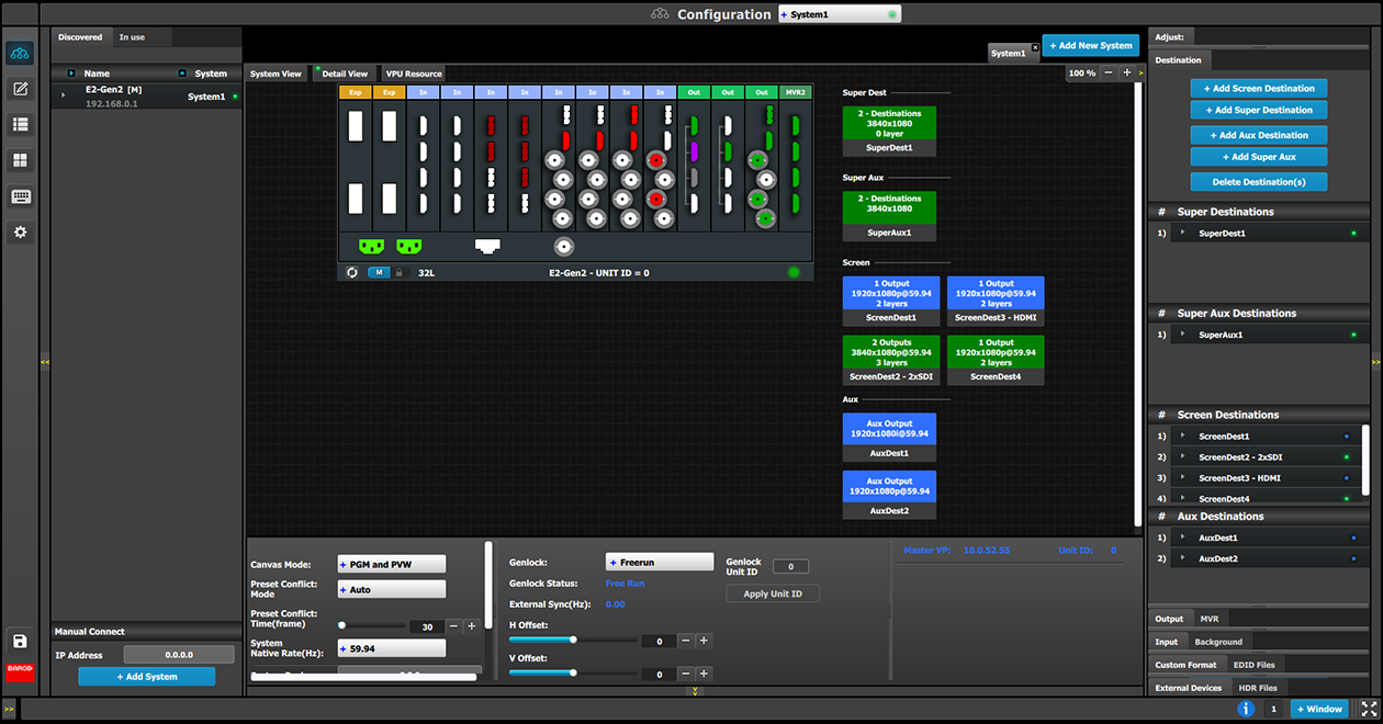
Super Destinations, Screen Destinations, and AUX Destinations are represented graphically in the Diagram area.
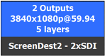 | Blue: The destination has been assigned to a super destination. |
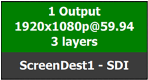 | Green: Output(s) have been assigned to the destination |
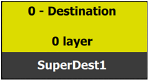 | Yellow: Output(s) have been removed from the destination. |
It is possible that after the unit is turned on, the hardware configuration can be altered making certain Destinations to have invalid Output configurations.
In this case the Destination in the System Diagram becomes grey and adjustment is disabled. In this case the destination needs to be deleted and new one created to reflect the existing output configuration.
As Screen Destinations can be understood as groups of outputs, Super Destinations can be understood as groups of Screen Destinations. Once a Super Destination and more than one Screen Destinations have been created, the Screen Destinations can be assigned to a Super Destination by dragging and dropping them on the Super Destination in the Diagram area of the Configuration menu. Local Layers added to a Screen Destination are added only to that Screen Destination, while Super Layers added to a Super Destination are also added to each Screen Destination in the Super Destination.
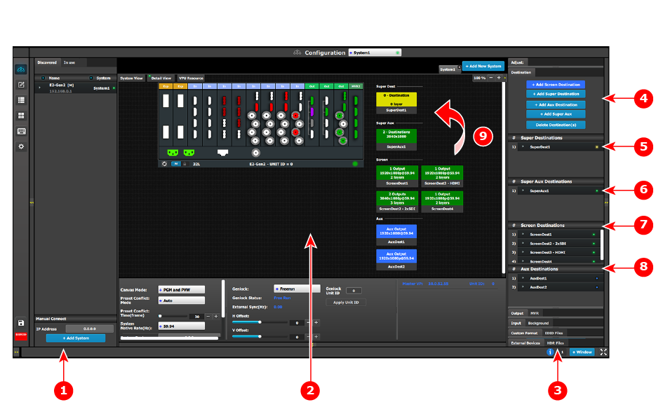
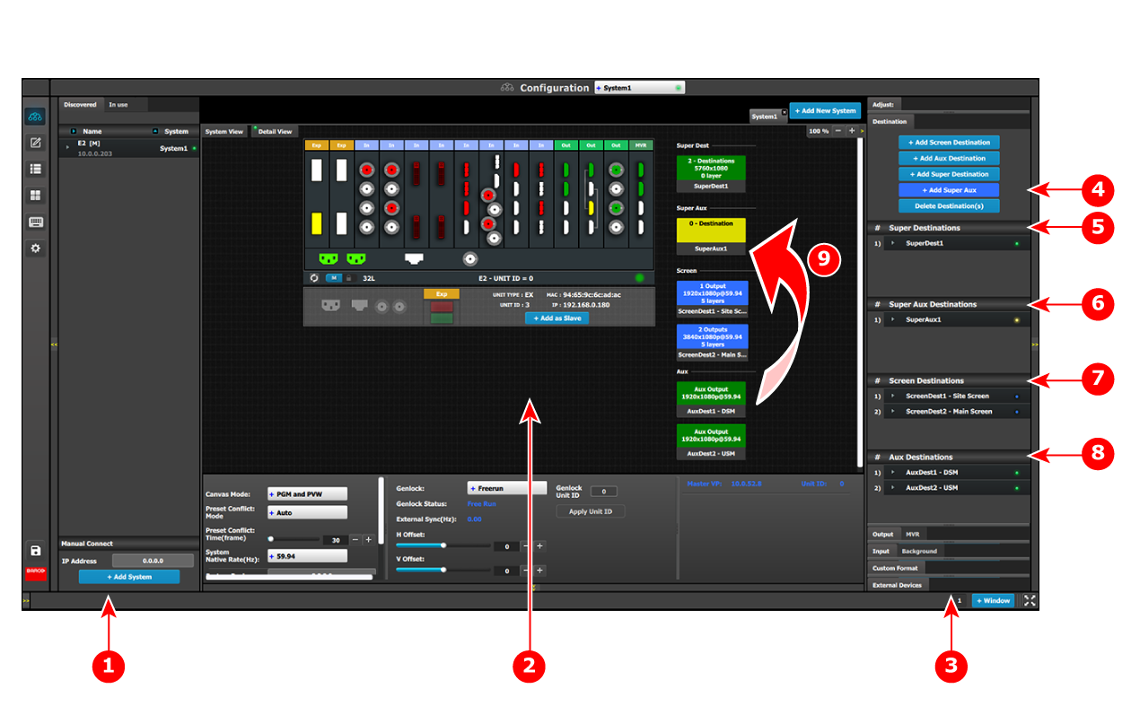
| 1 | Network resource area |
| 2 | System diagram area |
| 3 | Adjustment area |
| 4 | Add and delete Destination buttons
|
| 5 | SuperDest1 |
| 6 | SuperAux1 |
| 7 | Screen Destinations
|
| 8 | Aux Destinations
|
| 9 | Drag and drop ScreenDest1 and ScreenDest3 into SuperDest1. |
(Optional) Add Super Layers to Super Destinations and Local Layers to Screen Destinations.
Layers may be added to the Destinations after the Screen Destinations are assigned to the Super Destination.
In Image 6–25 Screen Destinations 1 and 3 have been assigned to Super Destination 1. (Layers have also been assigned to the Destinations.) Note that the colors of the Destinations in the System diagram area and the colors of the LEDs in the Adjustment area have changed to indicate that the Screen Destinations have been assigned to the Super Destination and that Layers have been assigned to the Destinations.
Use the Programming menu to manipulate Super and Screen Destinations.
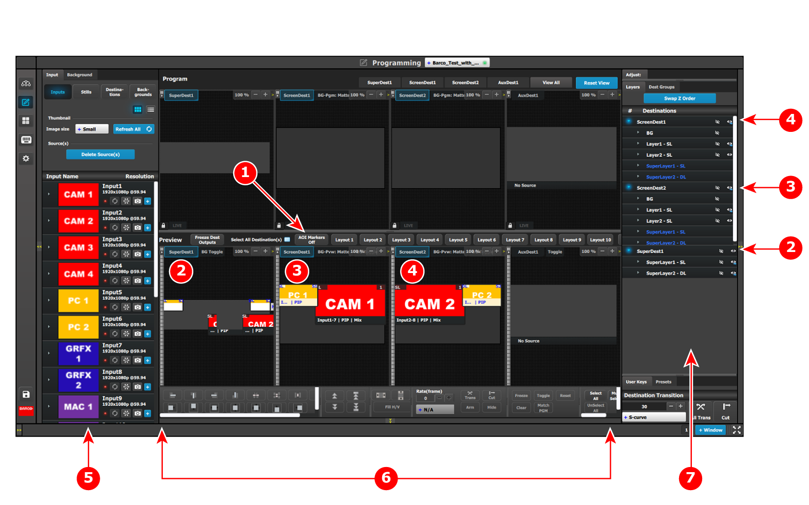
| 1 | AOI Markers “Off” |
| 2 | SuperDest1 |
| 3 | ScreenDest1 |
| 4 | ScreenDest2 |
| 5 | Resources area |
| 6 | Layer modification area |
| 7 | Adjustment area |
Set the AOI Markers to “Off.”
Turning on the AOI Markers "On" or "Off" affects how the Layer—modification functions (the Layer alignment buttons, including Fill H, Fill V and Fill H/V) work. With the AOI Markers set to "On," the Layer alignment buttons align the Layer into the Screen Destination in which the center of the Layer is located. With the AOI Markers set to "Off," the Layer alignment buttons align the Layer in the entire Super Destination.
Drag and drop Inputs from the Resources area to desired Destinations.
Adding an Input as a Super Layer to a Super Destination adds that Input to one or all of the Screen Destinations assigned to the Super Destination, depending on the placement of the Super Layer in the Super Destination.
Note: Source can be updated in a Destination by dragging and dropping a new source into the Destination or into the Super Destination of which the Destination is a part. This may also be done with Auxes and Super Auxes.
Apply Layer-modification shortcuts, User Keys, or Presets to Layers in the Super Destination or in the Screen Destinations.

Based on the Aux Capacity, the user can create AUX Destination on an output card. The AUX capacity defines the Input capacity and scaler size of the AUX.
All output cards can be used for Aux destinations
| Card Type | Aux Capacity Setting | № of Auxes per Card | Max Output Resolution |
| HDMI 1.4 | 2K (SL) | 4 | 2048x1200p60 |
| DL | 4 | 2048x1200p60 | |
| DL | 2 | 2560x1600p60 | |
| 4K | 2 | 3840x2160p30 | |
| 8L | 1 | 3840x2160p30 | |
| 3G-SDI | 2K (SL | 4 | 2048x1080p60 |
| DL | 4 | 2048x1080p60 | |
| 4K | 2 | 2048x1080p60 | |
| 8L | 1 | 4096x2160p60 (Quad Link 3G) | |
| DP 1.2 | 2K (SL) | 4 | 2560x1600p60 |
| DL | 4 | 2560x1600p60 | |
| 4K | 2 | 4096x2160p60 | |
| 8L | 1 | 4096x2160p60 | |
| HDMI 2.0 | 2K (SL) | 4 | 2560x1600p60 |
| DL | 4 | 2560x1600p60 | |
| 4K | 2 | 4096x2160p60 | |
| 8L | 1 | 4096x2160p60 | |
| Tri-Combo | 2K (SL) | 6 | SDI 2048x1080p60; DP/HDMI 2560x1600p60 |
| DL | 4 | SDI 2048x1080p60; DP/HDMI 2560x1600p60 | |
| 4K | 2 | SDI/DP/HDMI 4096x2160p60 | |
| SDI/DP/HDMI 4096x2160p60 |
As Super Destinations can be understood as groups of Screen Destinations, Super AUX Destinations can be understood as groups of AUX Destinations. Once a Super AUX Destination and more than one AUX Destinations have been created, the AUX Destinations can be assigned to a Super AUX Destination by dragging and dropping them on the Super AUX Destination in the Diagram area of the Configuration menu. AUX and Super AUX Destinations do not have Layers.
Add and delete Destination buttons
- Add Screen Destination
- Add Aux Destination
- Add Super Destination
- Add Super AUX
- Delete Destination(s)
Super Destinations
- SuperDest1
Super AUX Destinations
- SuperAux1
Screen Destinations
- ScreenDest1
- ScreenDest2
Aux Destinations
- AuxDest1
- AuxDest2
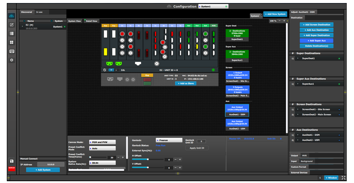
Drag and drop the AUX Destinations onto the Super AUX Destination(s).
Note: Source can be updated in an Aux by dragging and dropping a new source into the Aux or into the Super Aux of which the Aux is a part.
Use the Programming menu to manipulate Super AUX and AUX Destinations.
The following examples use a Super AUX Destination that contains nine AUX Destinations, arranged in a 3 x 3 matrix.
To view the Super AUX…
Select the Programming menu.
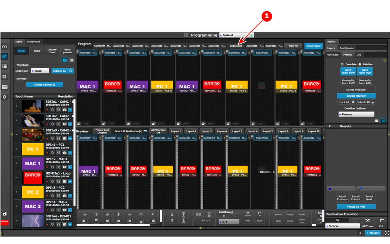
Select the SuperAux1 tab to view the Super AUX.
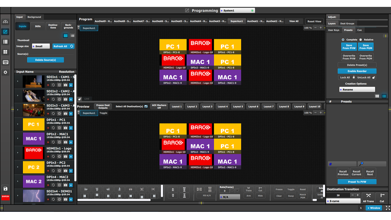
To tile a source over the entire Super AUX…
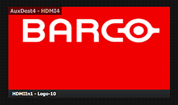
Double-click a source within the Super AUX.
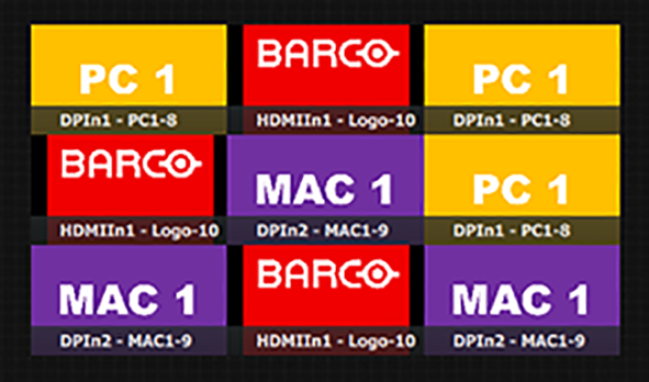
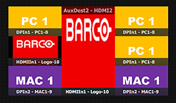
For example, double-clicking on the source that displays the Barco logo scales the Barco logo across the entire Super AUX.
To scale a source within the Super AUX…
Select a source within the Super AUX.
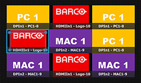
Drag the inner box of the selection box over the AUXes to be covered.
For example, drag the selection box over the other AUXes in the lower, left-hand quadrant.
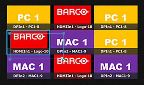
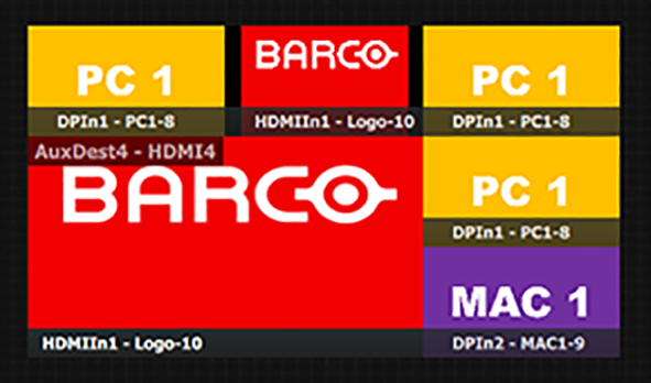
Release the selection box.
The selected source covers the four AUXes of the lower, left-hand quadrant.
To scale a source to any group of AUXes within the Super AUX…
Select a source within the Super AUX.
Drag the inner box of the selection box over the AUXes to be covered.
For example, drag the selection box over the other AUXes in the same row or column.
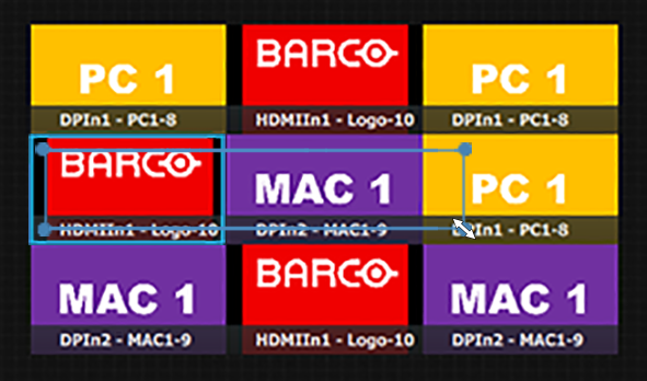
Release the selection box.
The selected source covers the other AUXes in the same row or column.
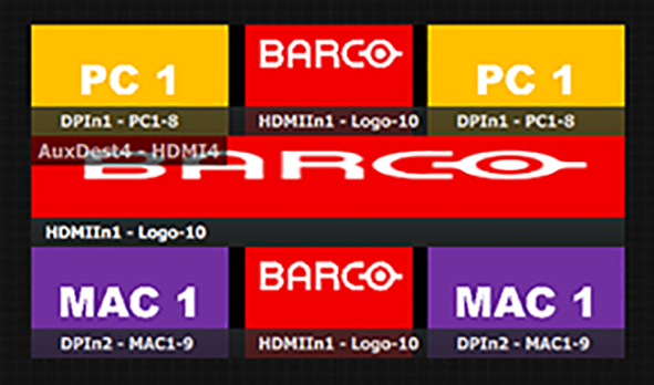
In the same manner an AUX can be vertically scaled in the Super AUX.