Flow chart


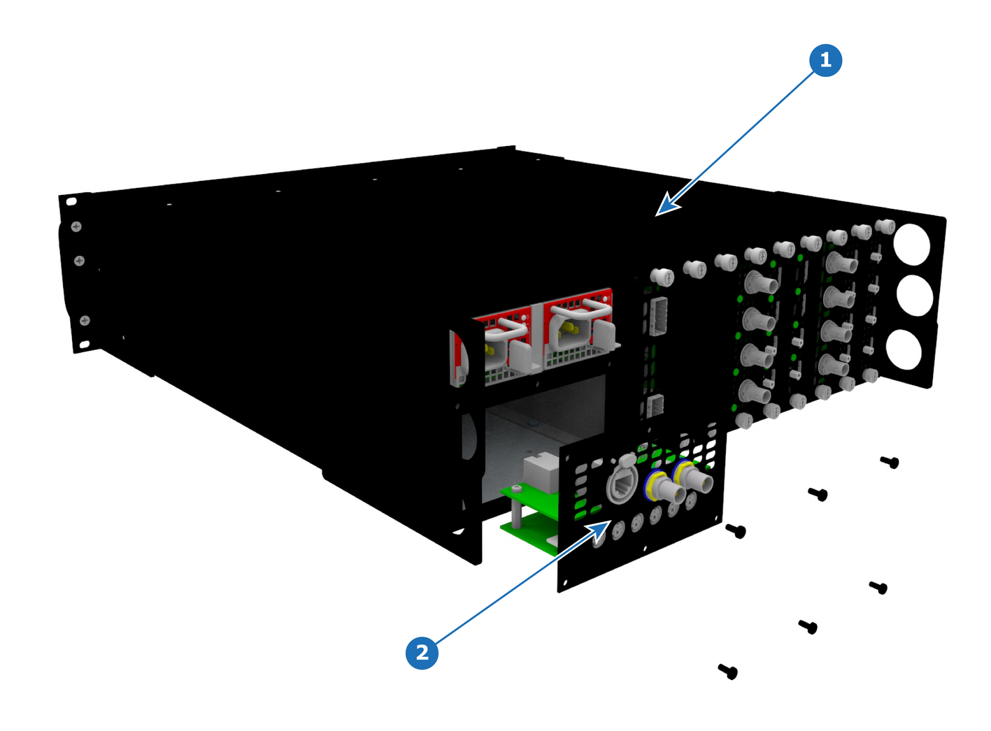
| GENLOCK/S3D S3 |
1 x Phillips Screwdriver #2
Remove the six pan head screws (4-40 X .25) that attach the Genlock assembly to the rear of the chassis.
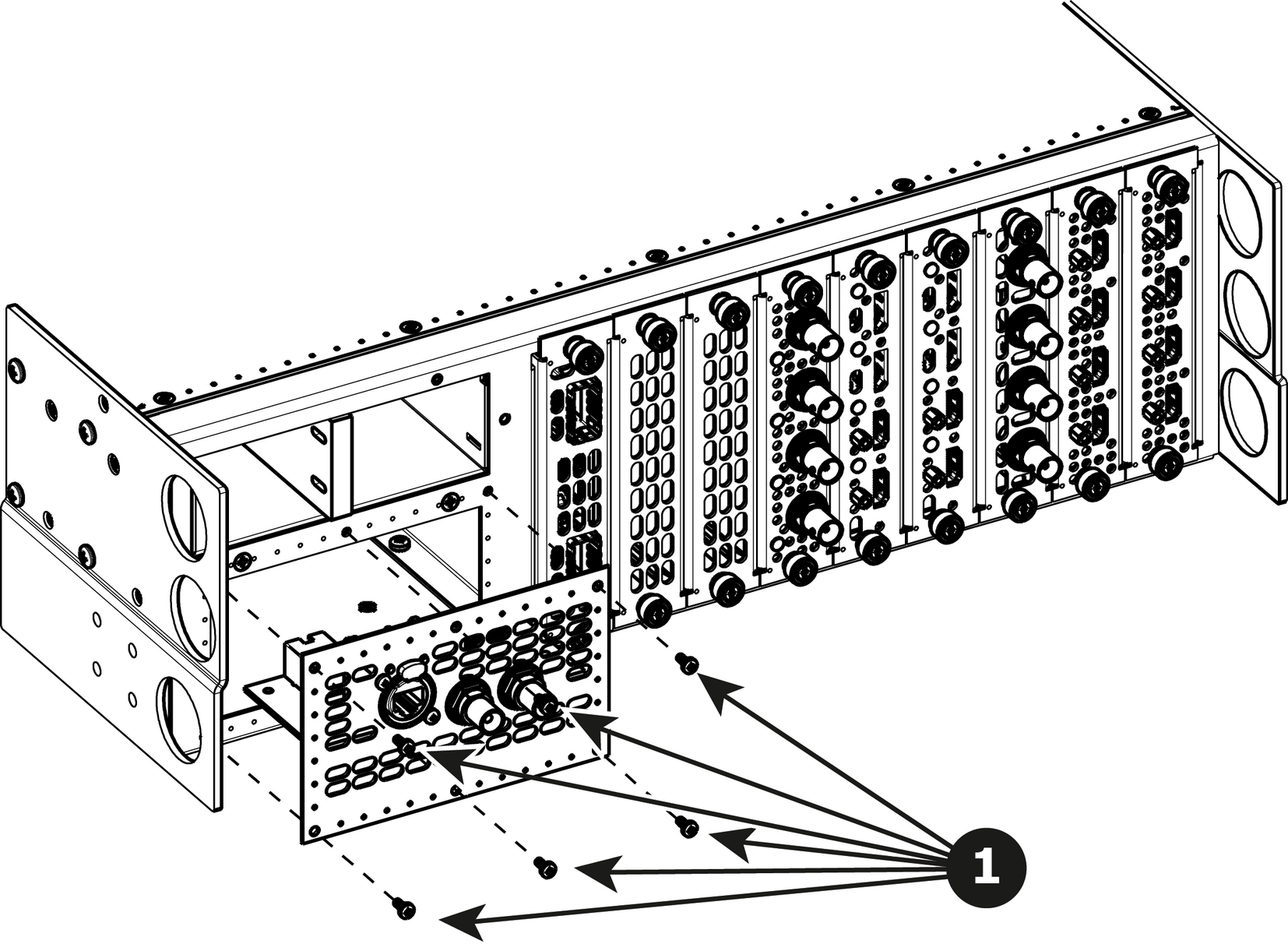
Gently pull the Genlock assembly away from the unit . Don't pull the assembly too far back because there are still 2 cables attached.

Unlatch the Genlock ribbon cable from the connector and pull it up and away from the Genlock board.
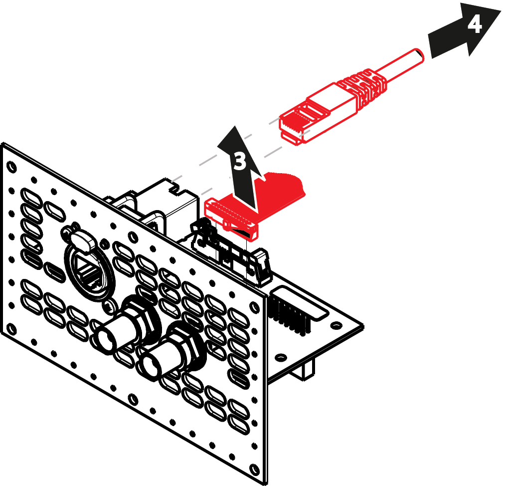
Unlatch the Ethernet cable from the connector and pull back and away from the Genlock board.
To install the Genlock Assembly follow the same procedure in the reverse order.