7.14 Configuration Menu > Add Screen Destinations & Layers
General
In this procedure, you will Add Screen Destinations from the defined outputs.
Prerequisite
- Ensure that you are familiar with the Configuration Menu. For details on this menu, please refer to chapter “Configuration Menu”

Note: If more than one Destination is utilized, repeat the below steps until all Destinations are added.
Add Screen Destinations
- Click on the Destination tab to define destinations for the configured outputs.
- From the diagram area click on the output that you want to be part of the new screen destination.
- Click on the +Add Screen Destination blue button to assign the output to a new screen destination.
- When the destination is created a green rectangle, with a label at the bottom of it, appears next to the unit diagram.
- If more than one output is to be assigned to the destination, such as a wide-screen projection blend, drag and drop any additional outputs into the destination rectangle. You will observe that the destination size is automatically updated as new outputs are added to the destination.
Note: An EMP allows only a certain mix of Screen (Program) Destinations and AUX Destinations. All Outputs can be AUX Destinations, or all Outputs can be assigned to Screen Destinations. Screen Destination sizes are determined by the available amount of pixel canvas, not by the number of Outputs assigned to a Screen Destination.
Add Layers to Destinations
With a screen destination selected, click on the Adjust tab that is located on the top of the adjustment panel.
Under the Assign sub-menu scroll down until you see the Layers section.
There are three radio buttons for layer size (SL, DL, and 4K) and two buttons for layer type (Mix and Single). Chose the combination of radio buttons from the two choices for the layer size and type you wish to add. The default selection is SL Mix Layer.
Click on the +Assign Layer to Destination blue button.
Click on this button as many times is required to add the layers you are assigning to the destination. Observe the number of layers indicated in the Layer box is incremented every time the add button is pressed. See also “Configuration Menu > Layer optimization”.
- If you need to delete layers, click on the Blue button Delete layers.
(Optional) Edit the Name
- Double click on “Destination1” in the Name list to edit the name.
- When the area turns blue, click the eraser icon to clear the field.
- Type a new name and press the Enter key when done.
(Optional) Adjust Destination Parameters
Click on the “Adjust” tab that is located on the top. In this Tab there are three sub tabs: Assign, Output and Wide (See below).
(Optional) Adjust Destination Parameters part 1 > Assign Tab
From this menu you can:
- Edit the name.
- Set the dimensions if more than one connector.
- Use the Auto Configure Output Format function that reads the EDID of the connected device and will produce a signal like that if still within the rules of VESA timings.
- Delete outputs (remove output(s) from the destination).
- Assign or Delete Layers.
(Optional) Adjust Destination Parameters part 2 > Output Tab
From this menu you can:
- See the output canvas (raster) size.
- See in what order and place the outputs populate the Destination.
- Select outputs for manipulation.
Choose more actions in sub tabs:
 Position:
- Enable Test Patterns with raster box and enable diagonal motion
- Define the Area of interest (AOI).
 Color:
- Perform color adjustments.
 Timing:
- Read the timing parameters associated with the selected format.
 Connector Settings:
- Select Color/Sample/Bit depth, colorimetry, etc.
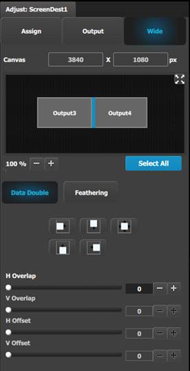
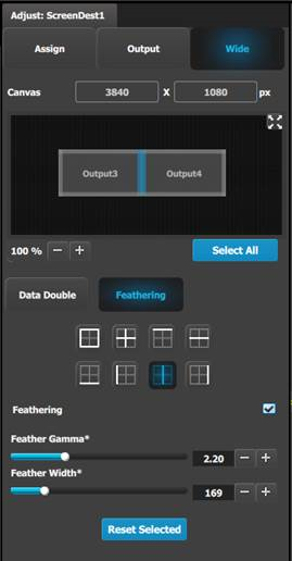
(Optional) Adjust Destination Parameters part 3 > Wide Tab
From this menu you choose between the two sub tabs:
(Optional) Delete Destinations
- Click on the blue button Delete Destination(s).
- From the Name list click on the “x” space next to the output(s) you wish to delete.
- Hit the red button. All of the selected Destination(s) will be removed from the list.