
16.6 Top Cover

Flow chart
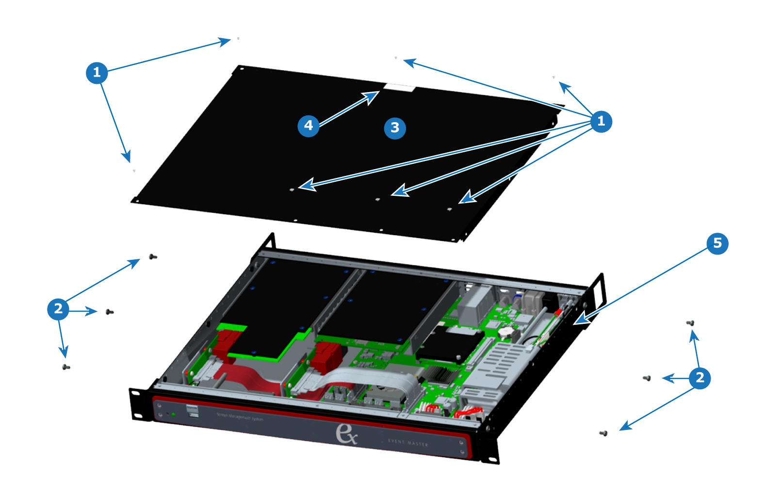
Image 16–6 Top cover
Overview
Image 16–7 Removal of EX top cover
1
Flat Head, 82° UC, 4-40 Screws
2
Pan Head, 6-32 Screws
3
Top cover
4
Tamper-evident label
5
Chassis
Concerned parts
EX Chassis
EX Chassis Cover
Tamper-evident Label
Flat Head, 82° UC, 4-40 Screw
Pan Head, 6-32 Screw
Necessary tools
How to remove the top cover
  1. Remove the seven flat head, 4-40 screws from the top of the unit.

    The middle screw along the rear edge of the top cover is under the tamper-evident label. Removing the screw may be easier, if you first remove the label.

  2. Remove the six pan head, 6-32 screws from the sides of the unit.
  3. Lift the top cover from the unit.
How to install the top cover

To install the top cover on the EX chassis, follow the steps of the removal procedure in reverse order.

Note: Apply Loctite 242 (or equivalent) thread-locker to the screws that attach the top cover to the chassis. Tighten the 4-40 flat-head screws to 5 in-lbs. Tighten the 6-32 pan-head screws to 8 in-lbs.