6.13 Configuration Menu > Adjustment > Input Configuration
General
In the Input configuration menu users can assign input connectors to inputs and adjust parameters to match the incoming signal format and timing parameters.
Input Card arrangement
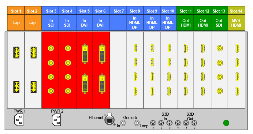
On the E2 model, the input cards occupy slots 3 through 10 and are right justified to slot 10.
On the S3–4K model, the input cards occupy slots 4 through 6 and are right justified to slot 6.
If there is an empty input slot between two input slots, all input cards to the left of the empty slot are marked with red. Red indicates that although the cards will operate properly, inputs from these cards will not be available at the Multiviewer.
Image 6–15E.g. E2 with an empty input-card slot
If the card in the slot is wrong type (e.g. output card in input slot, or vice versa) then the slot in the diagram will be greyed out.
Input Connector Grouping
The reason for connector grouping is that in order to accommodate higher resolutions with no loss of quality bandwidth has to be added to the signalpath. By combining connectors a higher resolution all the way up to 4K@60Hz with progressive scan can be added with its full color space 4:4:4.
Several rules apply when defining an input configuration:
An Input connector can only be assigned to one input configuration.
Multiple input connectors in the same configuration must be of the same type and in the same slot or in adjacent slots. For example, cannot have a HDMI connector and an SDI connector in the same input configuration.
An input can be configured from one, two, or four connectors.
A multi—connector input is still ONE input.
Maximum of 4 single link connectors can be assigned to an Input.
Maximum of 8 single link connectors can be assigned to a background, Background.
Maximum of 128 input configurations can be assigned.
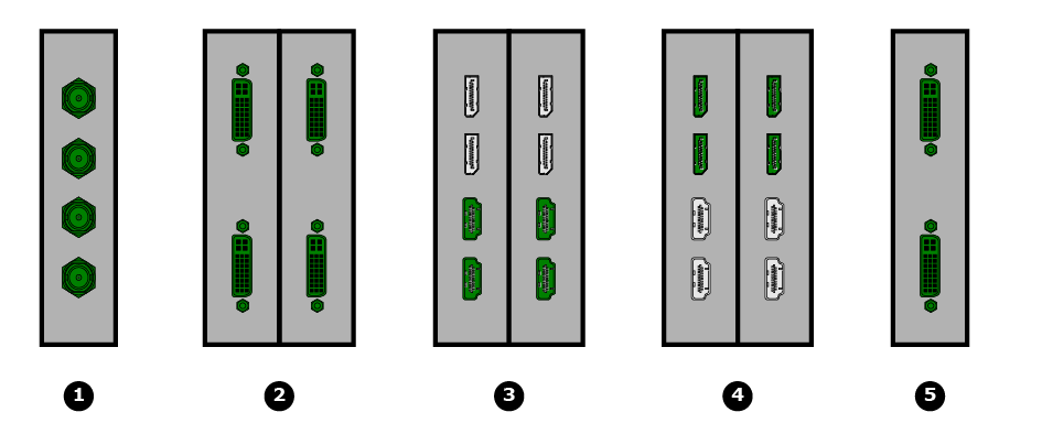
Examples of 4K Valid Inputs:
Image 6–16Valid 4K inputs
1
4x SDI-3G
2
4x DVI-SL
3
4x HDMI 1.4
4
4x DP 1.1
5
2x DVI-DL
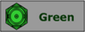
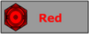
Input connector colors
Not assigned and no input signal is detected
Not assigned to any input, but a signal has been detected
Assigned to an input, and an input signal is detected
Assigned to an input, but an input signal is not detected
Input configuration menu description
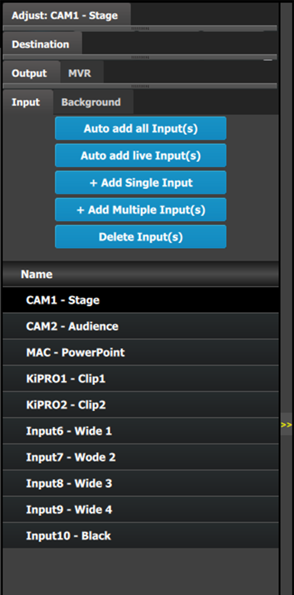
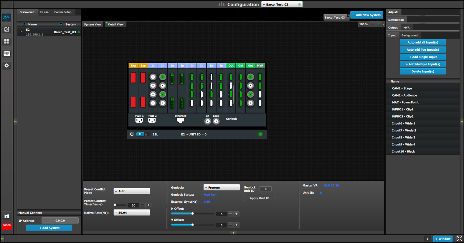
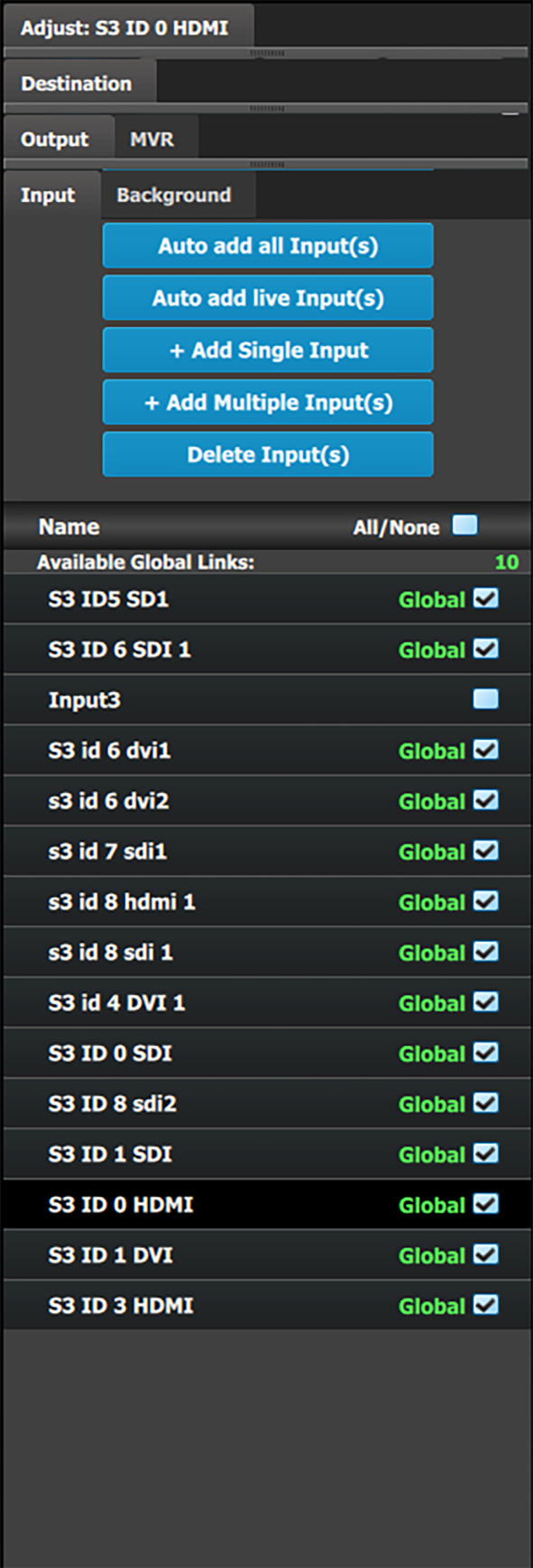
Input configuration menu is accessed by clicking on the Input tab.
This menu provides:
Auto Add all Input(s): A button to automatically allocate all unassigned input connectors to an input.
Auto add live Input(s): A button to automatically allocate all LIVE input connectors (YELLOW) as configured inputs.
+ Add Single Input: A button to manually allocate connectors to an Input configuration.
+ Add Multiple Input(s): A button to manually allocate more than one connector to separate Input configurations.
Delete Inputs: A button to delete unused or obsolete inputs.
A list of all the Inputs already created on the system (e.g. Cam 1, Input2).
Note: Users can now link more than two E2s, or more than two S3–4Ks in a single system. In this configuration, only input expansion is supported. Users can select up to 48 SL inputs for linked E2 systems and 24 SL inputs for linked S3–4K systems to be marked it as a "Global Input."
Global Input checkboxes are available in the Configuration page, under the Input and Background tabs for inputs.
How to Auto add all Inputs
The “Auto add all Inputs” button automatically allocates all unassigned input connectors as individual, single link input configurations. At this moment the incoming signal is acquired and a source file is saved. Input connectors that are already assigned to an input will not be affected. If the button is pressed, all previously unassigned input connectors will be automatically assigned. The software by default names inputs as [ConnectorType] “Input 1, 2, 3….”. Input configuration names can be renamed by double-clicking on the name and turning the box blue.
How to Auto add live Inputs
The “Auto add live Inputs” button automatically allocates all live input connectors as individual inputs. Input connectors that are already assigned to an input will not be affected. If the button is pressed in the beginning, before any sources have been connected, no inputs will be automatically assigned. The software by default names inputs as [ConnectorType] “Input 1, 2, 3….”. Input configuration names can be renamed by double-clicking on the name and turning the box blue.
The “Auto Add Live” feature adds only single-connector inputs. Any special input, such as a multi–connector 4K Input, needs to be assigned manually. See How to add Input section below.
How to add an Input
Inputs configurations can be added manually to un-assigned connectors.
Select the Detail View tab in the system diagram area.
Select an unassigned (white or yellow) input connector from the detail view.
More than one input connector may be selected. The connector(s) will be highlighted blue.
Note: If the input signal is 4K provided by the 4 SDI connectors, 4 SDI connectors need to be selected.
Click on the Add Single Input button.
How to delete Input
Click on the Delete Input(s) button
The Delete Input(s) button is replaced by the Delete Selected button (highlighted in red).
Click on the corresponding connector in the graphical area.
or
click in the “x” on the right hand side in the input configuration list.
Connector(s) is immediately highlighted in blue.
The deletion is completed by clicking the Delete Selected button.
Note: Multiple connector configurations can be selected to be deleted together.
How to access to the Input configuration adjustments
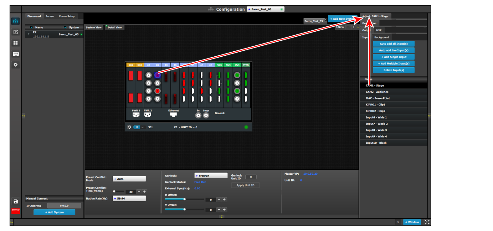
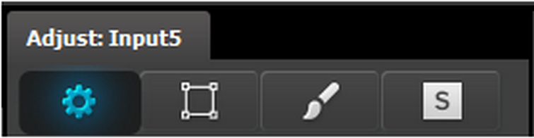
Adjustments to inputs are performed in the “Adjust” panel:
Select the input from the configuration list
or
clicking on the connector graphic.
An input is selected.
Click on the Adjust tab that is on the top of the Adjustment area.
Image 6–18Accessing the Input Adjust panel
The input adjustment panel is displayed.
Input adjustment panel description
The input adjustment panel is divided in four sections.
Main page
Format & Timing
Color Adjustment
Contact Information
Input adjustment panel > Main page
This menu is available in two versions according to the input type:
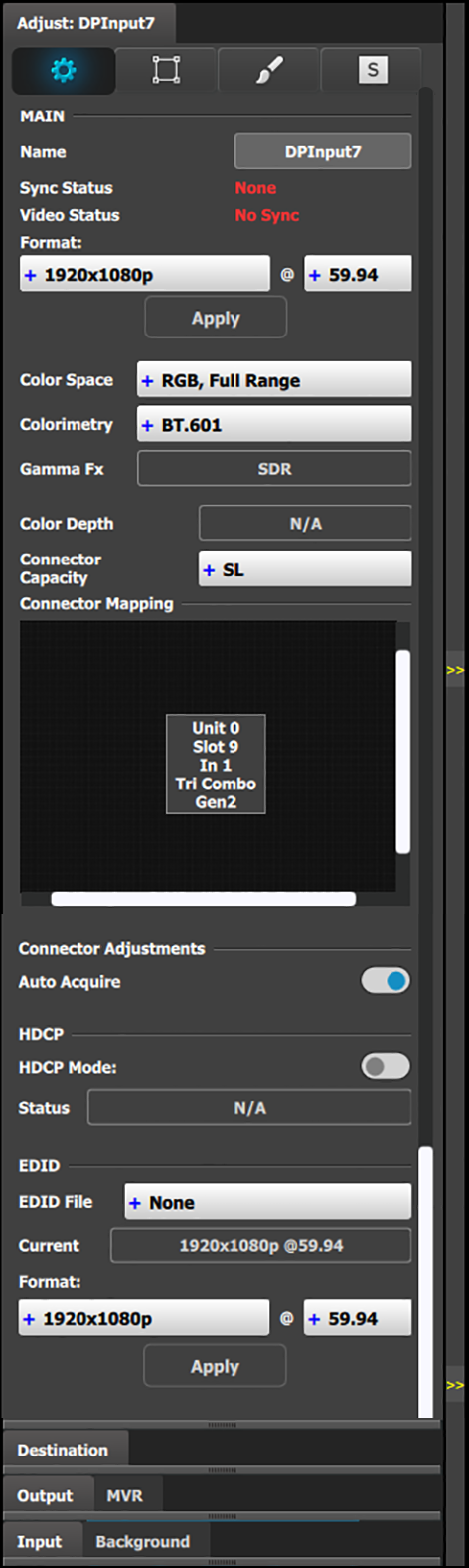
• DVI, HDMI and DisplayPort input types – top half
Name: Edits the name of the input configuration.
Sync Status: Detects a good video sync.
Video Status: Indicates if the connector capacity is in par with the input resolution.
Format: The detected video format is shown here. If Auto Acquire is unchecked below, the desired input video format is selected here from the drop-down menu.
Color Space: The detected color space is shown here. In the event of a non-VESA standard source the color space can be unmatched to the processing. In this case a different color space can be selected to accommodate the signal. Available are:
RGB, Full Range
RGB, Reduced Range
SMPTE, Full Range
SMPTE, Reduced Range
Colorimetry: Choose the colorimetry ITU-R recommendation for the output.
Available recommendations are:
BT.601 (SDTV)
BT.709 (HDTV)
BT.2020 (UHD)
DCI-P3 (digital movie projection)
Gamma Fx: Choose the Gamma format for the output.
Gamma Fx values are:
SDR
HLG
PQ/HDR10
Color Depth: This field displays the color bit depth of the input signal in number of bits per pixel.
Connector Capacity: Each connector has the option to accommodate different bandwidth standards over its interface. This is referred to as:
NONE The connector is turned off and cannot accept any video, bandwidth of this connector is freed up to be used by another connector. Connector is grayed out in the graphic representation. Connectors may need to be selected to NONE before DL or 4K can be selected on others.
SLSingle Link The connector can accommodate a resolution up to 2048 x 1200@60Hz.
Connector Capacity (continued):
DLDual Link The connector can accommodate a resolution up to 2560 x 1600@60Hz.
Note: A dual link connector can also accommodate a 3840 x 1080 or 2048 x 2160 signal, that is also available in the EDID list once DL is selected for that input.
4K The connector can accommodate a resolution up to 4K@60P.
Note: On a Gen 1 input card, in order to accommodate a 4K@60 signal, 2 or 4 connectors need to be used.
Connector Mapping: Shows the Unit ID, slot number, the connector number in the slot, and type of input card.
Auto Acquire: Enables the auto acquire mode. During acquisition, the system detects and acquires the input type and resolution. Refer below for details regarding this feature. Default is On
Inputs auto acquire incoming video as standard. If the setting is unchecked, only the set or previously acquired signal will be valid video.
HDCP Mode
Enables the HDCP setting for the selected input.
The default for DisplayPort, DVI, and HDMI inputs is Off. To turn On the HDCP Mode, click on the empty checkbox. When the checkbox displays a check mark, HDCP Mode is On. HDCP Mode is not applicable to SDI inputs.
EDID
All inputs (except SDI) can have an EDID (Extended Display Identification Data) set according to its connector capacity. The currently set EDID is visible in the Current box.
Format: The drop-down menu with its search function provide a way to select any of the available VESA or SMPTE standard EDIDs as well as a frame rate. Once selected the Apply Button needs to be pressed in order to program the inputs.
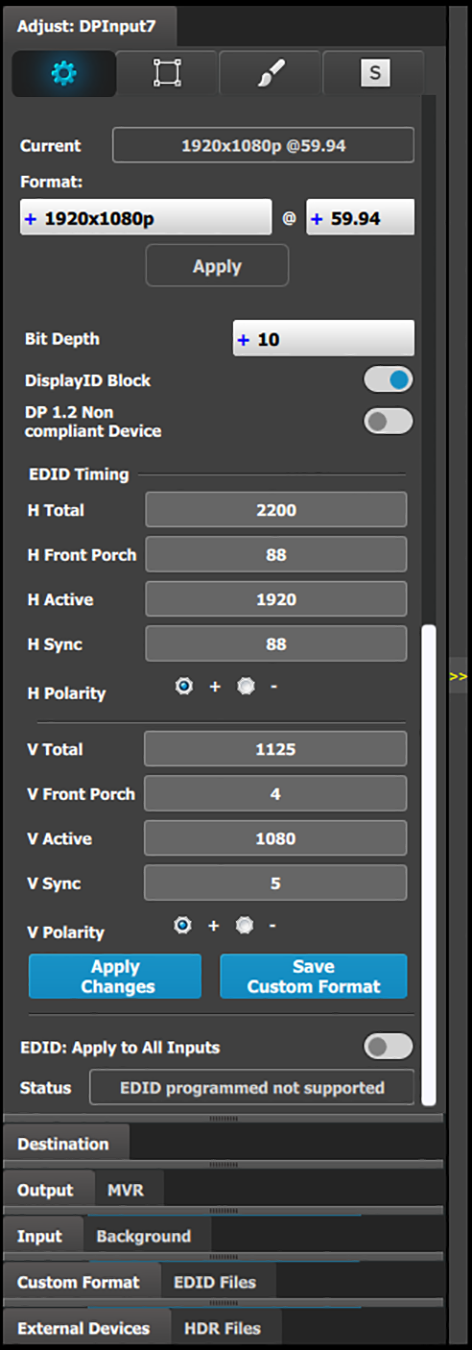
• DVI, HDMI and DisplayPort input types – bottom half
Bit Depth: User-selectable bit depth for use with custom EDID.
DisplayID Block (for DP 1.2 inputs only): When this checkbox is checked, the EDID is programmed with a "Tiled display topology" data block. This is useful for multi connector input configurations. Do not enable this feature if the input is a single input configuration.
DP 1.2 Non-compliant Device: Select to indicate that the device is not compliant with the DisplayPort 1.2 specification.
EDID Timing: The EDID timing can be edited into a non standard, or Custom EDID by double clicking on each timing box and inserting a value. A EDID timing needs to follow the VESA rules, and typically a VESA calculator needs to be used.
Once a value is inserted ENTER needs to be pressed.
Selected EDID or Custom EDID can be applied to all inputs of the same type at once by selecting the checkbox towards the end of the panel.
Apply Changes button: Applies changes to the current input format.
Save Custom Format: Saves changes to a custom format.
EDID: Apply to All Inputs: Applies the current format to all inputs.
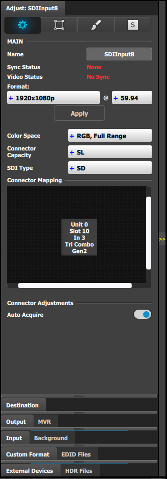
• SDI input type
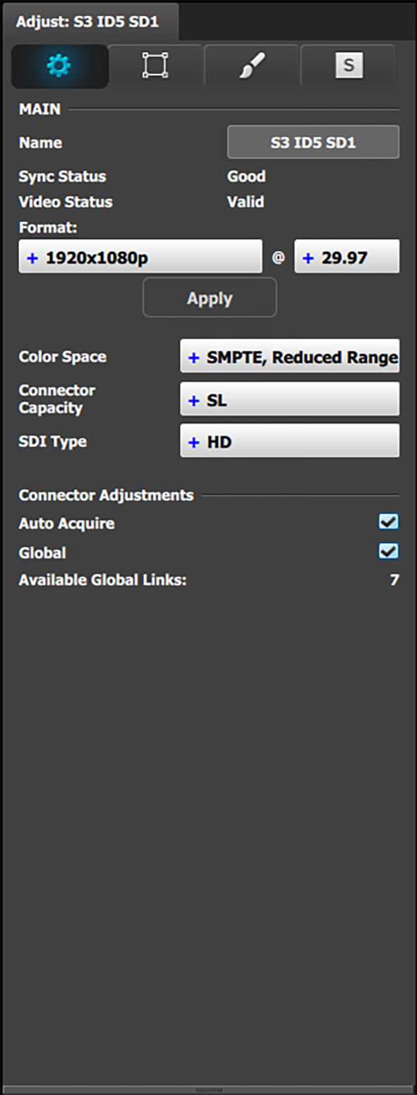
The SDI input configuration menu is similar to the DVI/HMDI/DP menu but without the EDID and HDCP sections. In addition the SDI menu includes an addition selection regarding the SDI type.
Name: Edits the name of the input configuration.
Sync Status: Detects a good video sync.
Video Status: Indicates if the connector capacity is in par with the input resolution.
Format: The detected video format is shown here. If Auto Acquire is unchecked below, the desired input video format is selected here from the drop-down menu.
Color Space: The detected color space is shown here. In the event of a non-VESA standard source the color space can be unmatched to the processing. In this case a different color space can be selected to accommodate the signal. Available are:
RGB, Full Range
RGB, Reduced Range
SMPTE, Full Range
SMPTE, Reduced Range
Connector Capacity: Each connector has the option to accommodate different bandwidth standards over its interface. This is referred to as:
NONE The connector is turned off and cannot accept any video, bandwidth of this connector is freed up to be used by another connector. Connector is grayed out in the graphic representation. Connectors need to be selected to NONE before DL or 4K can be selected on others.
SLSingle Link The connector can accommodate a resolution up to 2048 x 1080@60Hz.
4K The connector can accommodate a resolution up to 4K@60P.
Note: On Gen 1 input cards, in order to accommodate a 4K@60 signal, 2 or 4 connectors need to be used.
SDI type (available with SDI connector type) : allows a choice between SD (297 Mb); HD (1.5Gb); 3G (3Gb) Level A, Level B, Level A 2SI, or Level B 2SI; 6G (6 Gb); or 12G (12 Gb). The 6G and 12G settings are available only for the SDI inputs on the Tri-Combo Input card.
The SDI Type options vary, depending on the format of the input signal. For example, for:
NTSC/PAL—the SDI Type can be only SD.
1080i or 1080p, with a refresh rate less than or equal to 30 Hz—the SDI Type can be only HD.
1080p, with a refresh rate greater than 30 Hz—the SDI Type can be:
Level A (default)
Level B
Level A 2SI
Level B 2SI
The 2SI options are available only if the Input/Output configuration has 4 SDI connectors from the same card, and the Output format is either 1920 x 1080 or 2048 x 1080.
Auto Acquire Feature discussion:
When the Auto Acquire is On, the system performs a full sync acquisition on the input signal whenever:
You select an input
The input type changes
The sync rate of the input signal changes
During acquisition, the system detects and acquires the input type and resolution When Auto Acquire is off, the system uses the last known configuration, when possible. If the input signal is incompatible with the saved configuration, a good input lock may not be possible. In this case, the format name field in the Status Menu displays the Invalid Signal message.
Please note the following important points regarding Auto Acquire:
It is recommended that you turn Off Auto Acquire in applications where you have already configured and saved the system’s input setup.
If Auto Acquire is On and a valid input is selected that does not have a saved input associated with it, the system attempts to detect and acquire the source. This process may take a few moments.
If Auto Acquire is Off, the system uses the last-known configuration for each input, to the extent possible, comparing the input’s timing to the configurations in the system’s library. These configurations can be custom files or system default configurations.
Most users can leave Auto Acquire on. Advanced users who know the input video timing parameters may choose to turn Auto Acquire off and select the parameters manually.
Input adjustment panel > Format & Timing
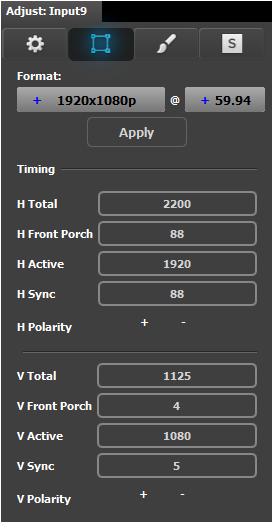
This is a status and informational menus. No adjustments can be done on this Format and Timing panel.
Format: Video format of the input
H Total: Total pixel count per line
H Front Porch: The offset between the end of the active area and the beginning of H sync
H Active: The horizontal size in pixels of the active area
H Sync: H sync width in pixels
H Polarity: Polarity (active High or Low) of the horizontal sync pulse (N/A in SDI)
V Total: Total line count per frame
V Front Porch: The offset in lines between the end of the output active area and the beginning of V sync
V Active: The vertical size of the output active area
V Sync: V sync width in lines
V Polarity: Polarity (active High or Low) of the vertical sync pulse (N/A in SDI)
Input adjustment panel > Color Adjustment
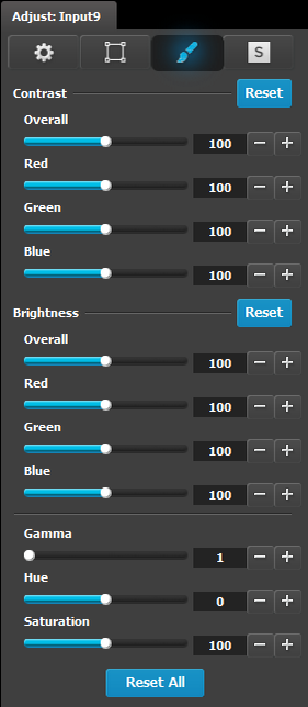
This menu allows for color adjustments for each input.
The RGB Contrast and Brightness settings are adjustable.
The Overall adjustment has a range of 50 to 150.
The individual Red/Green/Blue adjustments have a range of 25 to 150.
The default setting for all of these properties is 100.
Gamma is adjustable within a range of 0.31 to 3.29. The default setting is 1.0.
Hue is adjustable within a range of –90 to +90 degrees. The default setting is 0 degrees.
Saturation is adjustable within a range of 0 to 150. The default setting is 100.
Reset All changes all values to their default settings.
Input adjustment panel > Contact Information
This menu allows for the user to enter contact information for easy identification.