14.4 Rear I/O and Link Cards

Flow chart
Image 14–3
Overview
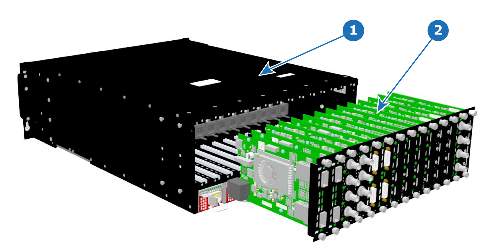
Image 14–4
1
Chassis
2
I/O and Link Cards
Concerned parts
DVI Input
SDI Output
SDI Input
HDMI Output
DP/HDMI Input
DVI Output
Link Card
Quad DP 1.2 Output Board
Tri-Combo Input
Tri-Combo Output
Quad HDMI Input Board
Quad HDMI 2.0 Output Board
Quad DP 1.2 Input Board
Necessary tools

Phillips Screwdriver #2.

How to remove a card
  1. Locate the card you wish to replace.

    Note: There are 14 card slots. The first slot on the left is slot 1 and the last slot on the most right position is 14.
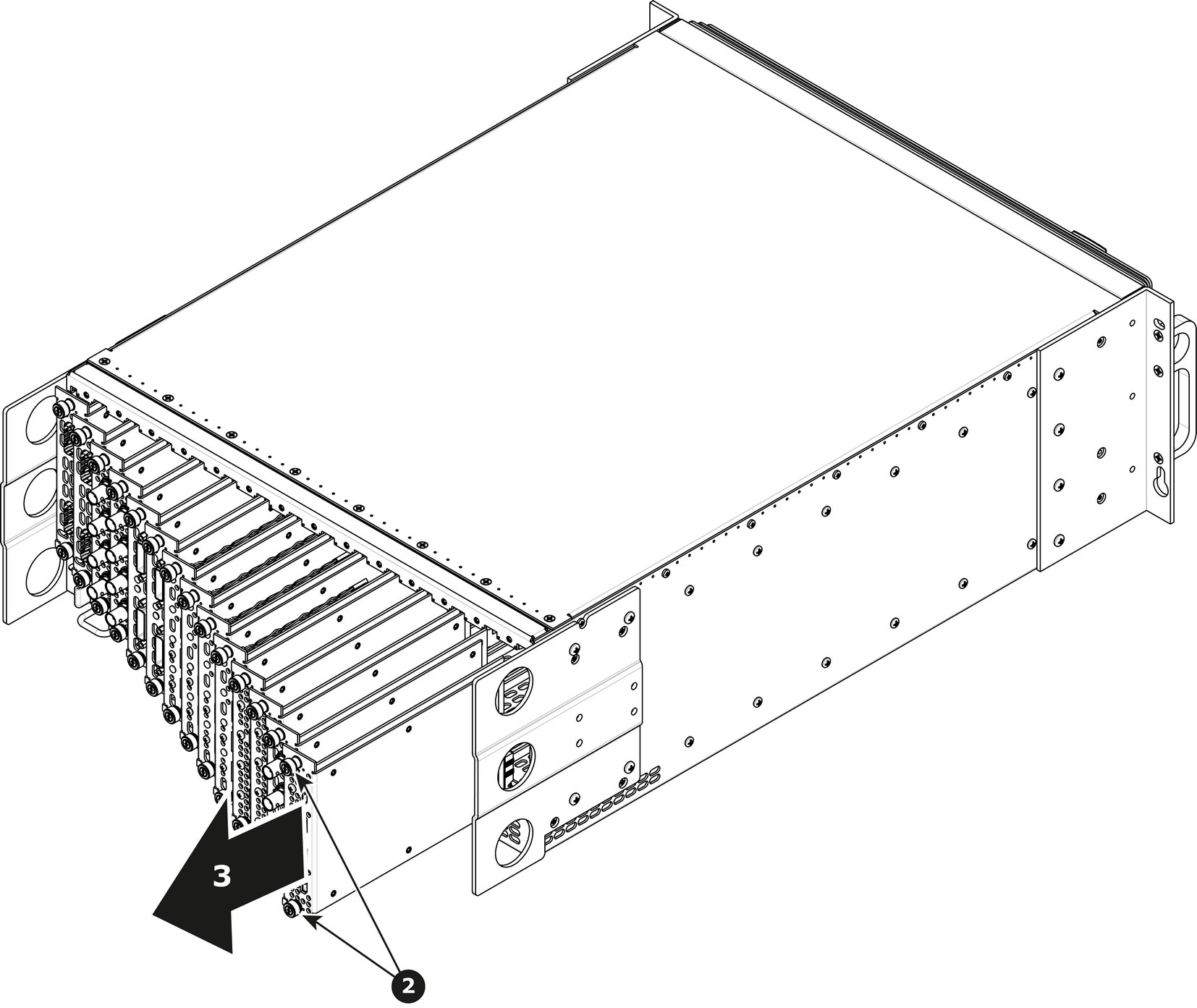
  2. Loosen and unscrew the top and bottom thumbscrews that are holding the card to the chassis.
  3. Gently pull the card out of its slot.

    Tip: You may need to wobble it a little bit up or down to loosen it from the card guides as you are pulling out.
    Image 14–5
How to install a card

To install a card follow the same procedure in the reverse order.

Note: Apply a little pressure on the card until it is fully inserted in the back plane connector.