Overview
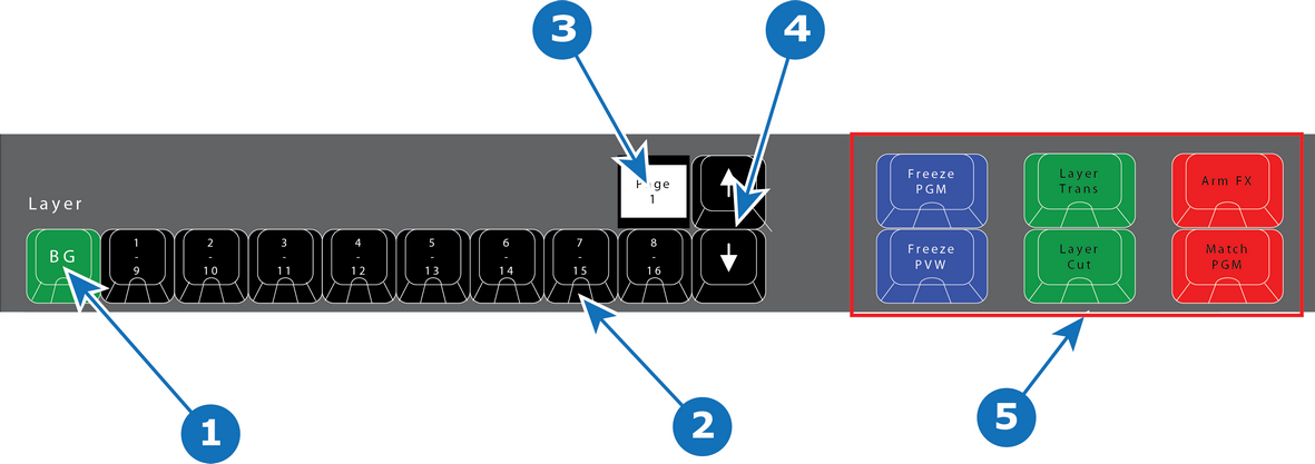
- 1
- Background button + 8 Layer buttons.
- 2
- LED (Red or Green).
- 3
- Layer range display (show the range of buttons — 1–8, 9–16, etc.).
- 4
- Arrow buttons (Layer range: up and down).
- 5
- Layer Operator buttons.

The system supports 9 Layer buttons with 13 pages (up to Layer 104). The red or green LEDs under these buttons indicate the selection of layers. The first button is ALWAYS background layer and therefore marked BG.
LED color under Layer buttons are RED and GREEN:
| LED color | Description |
| Red | Selected on PGM |
| Green | Selected on PVW |
Buttons 2 – 9 are marked 1 through 8 along the top row and 9 through 16 along the bottom row of their labels.
The Layer range display above the button marked 8/16 will show the range of buttons 1 – 8, 9 – 16, etc. Use the Arrow (up and down) to change the range.
Layer Operator Buttons
The six larger buttons to the left of the Layer buttons are Layer Executor buttons mapped to the corresponding functions in the EMTS. These are further explained below in chapter “Controller Operation”.