
14.7 Front Cover Assembly

Flow chart
Image 14–17
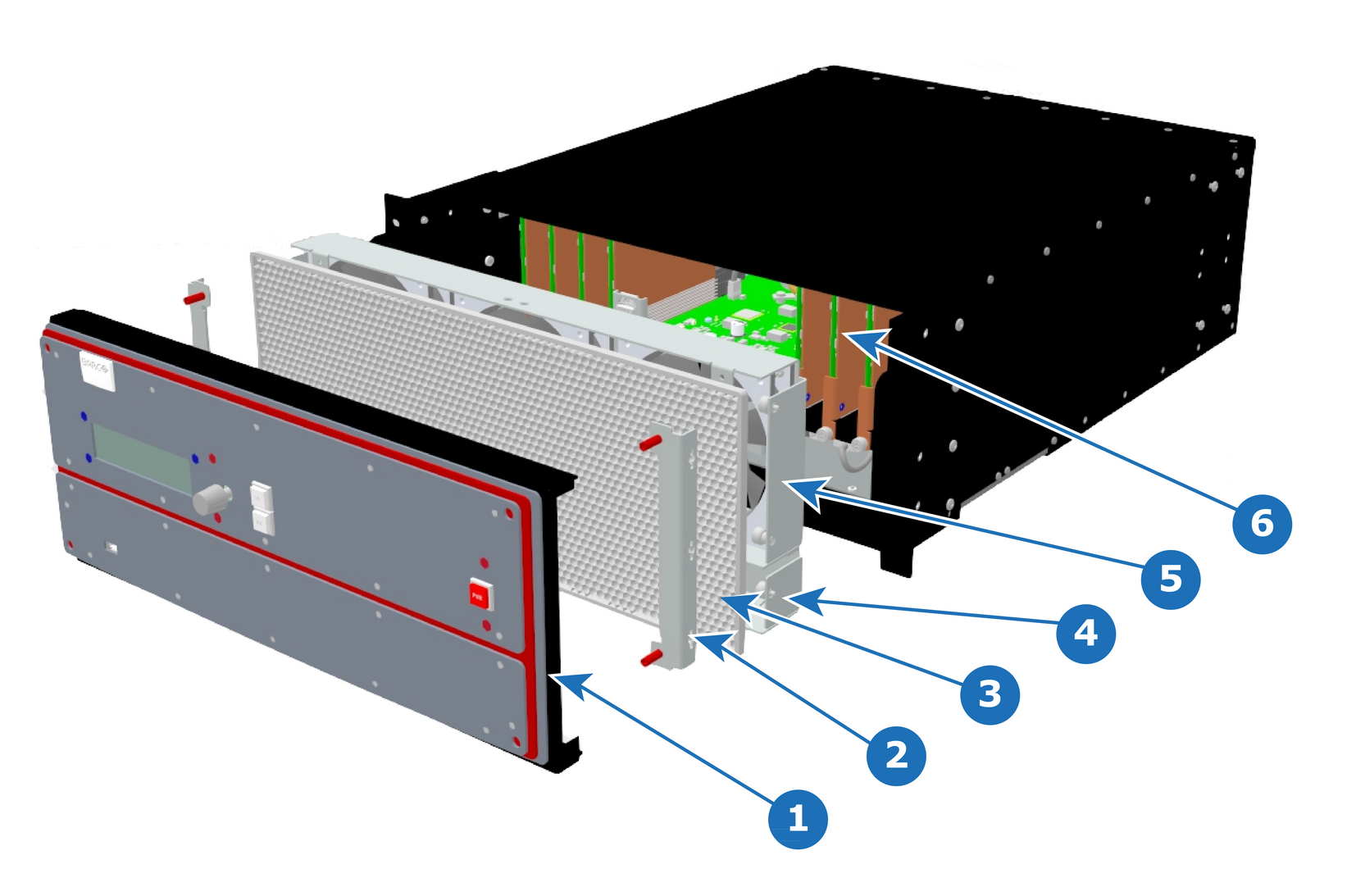
Overview
Image 14–18
1
Front Cover Assembly
2
Front Brackets
3
EMI Filter
4
1RU Fan Tray
5
3RU Fan Tray
6
VPU Cards
Note: The EMI filter is no longer needed, and it can be removed. If the EMI filter is left in place, it requires servicing. See “E2 maintenance actions”.
Necessary tools

1 x Screwdriver HEX 0.05" 7.05" (Provide by Barco in the original package).
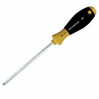
Image 14–19
How to remove the Front Cover Assembly
  1. Use the Hex screwdriver to remove the 4 screws (Hex 6-32x.25) that attach the front cover to the brackets located behind it.
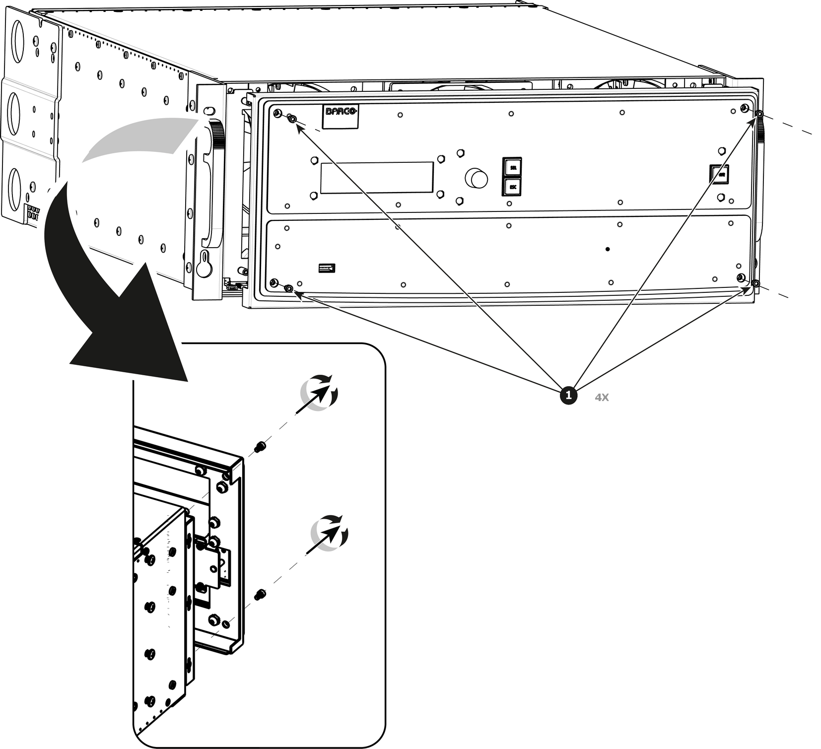
    Note: the standoffs go through the holes in sheet metal to properly align the front enclosure.
    Image 14–20
  2. Pull out the Front cover and lay it flat in front of the unit.

    At this point there are still 3 cables connecting the Front cover to the unit.
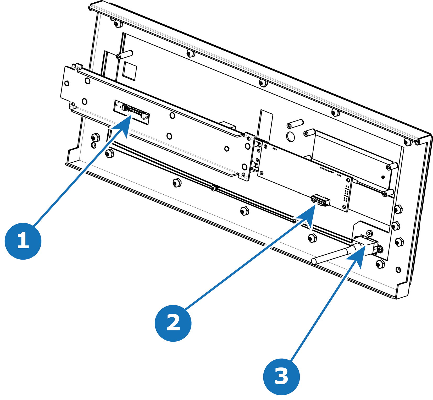
    Image 14–21
    1
    Front Panel Connector
    2
    VFD Connector
    3
    USB Connector
  3. Pull the latches away from connectors and gently pull the flat Front Panel away.
  4. Remove cables as outlined in the related procedures (VFD, USB and Front Panel connectors).
How to install the Front Cover Assembly

To install the Front Cover Assembly follow the same procedure in the reverse order.