14.22 System-Power Board

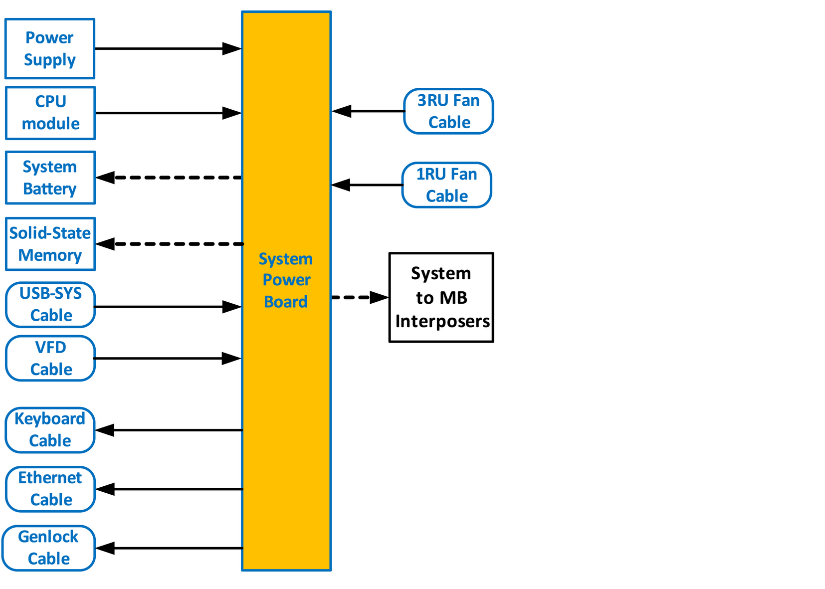
Flow chart
Image 14–63
Note: Before you proceed removing the System-Power board you need to remove the Power Supplies, Bottom Panel and the CPU board. Follow the instructions provided in these sections.
Overview
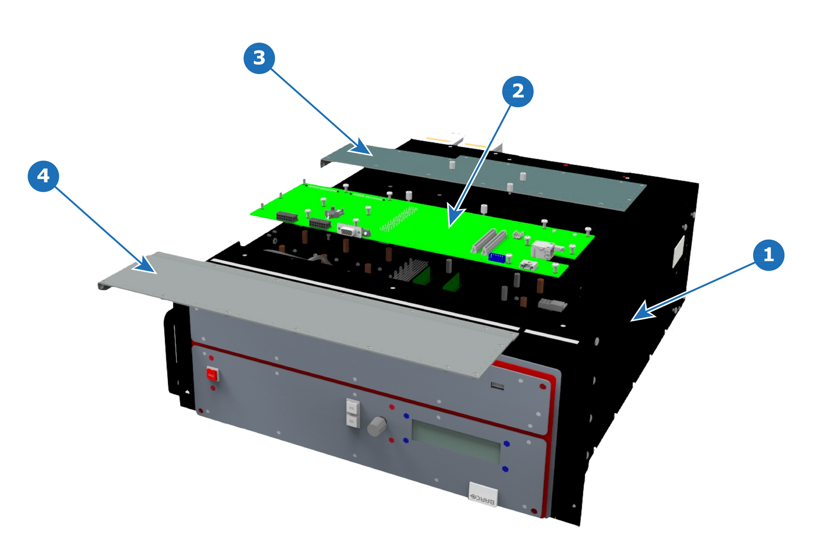
Image 14–64 System power board – E2 Gen 1
1
Chassis
2
System-Power Board
3
Bottom Panel part 1
4
Bottom Panel part 2
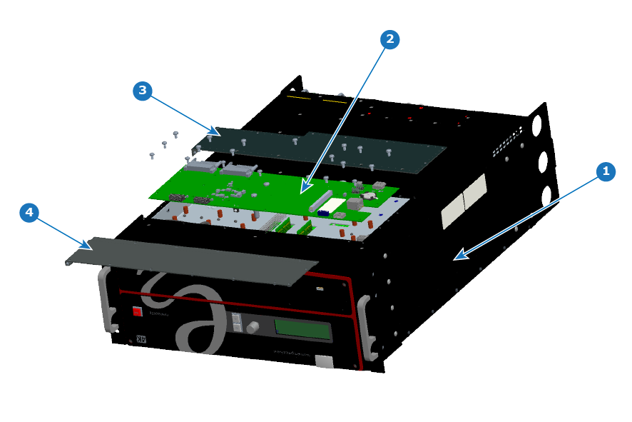
Image 14–65 System power board – E2 Gen 2
1
Chassis
2
System-Power Board
3
Bottom Panel part 1
4
Bottom Panel part 2
Concerned parts
System-Power Board
Necessary tools
How to remove the System-Power board
  1. Unplug the USB, VFD, 3RU and 1RU cables that are plugged on the top side of the board and are visible when the bottom panel is removed. Refer to the drawing below (top side) to locate the cables.
  2. With the Hex Screwdriver, remove the 5 standoffs (m 2,5 H6 Stainless Steel) which attach the CPU module to the motherboard.
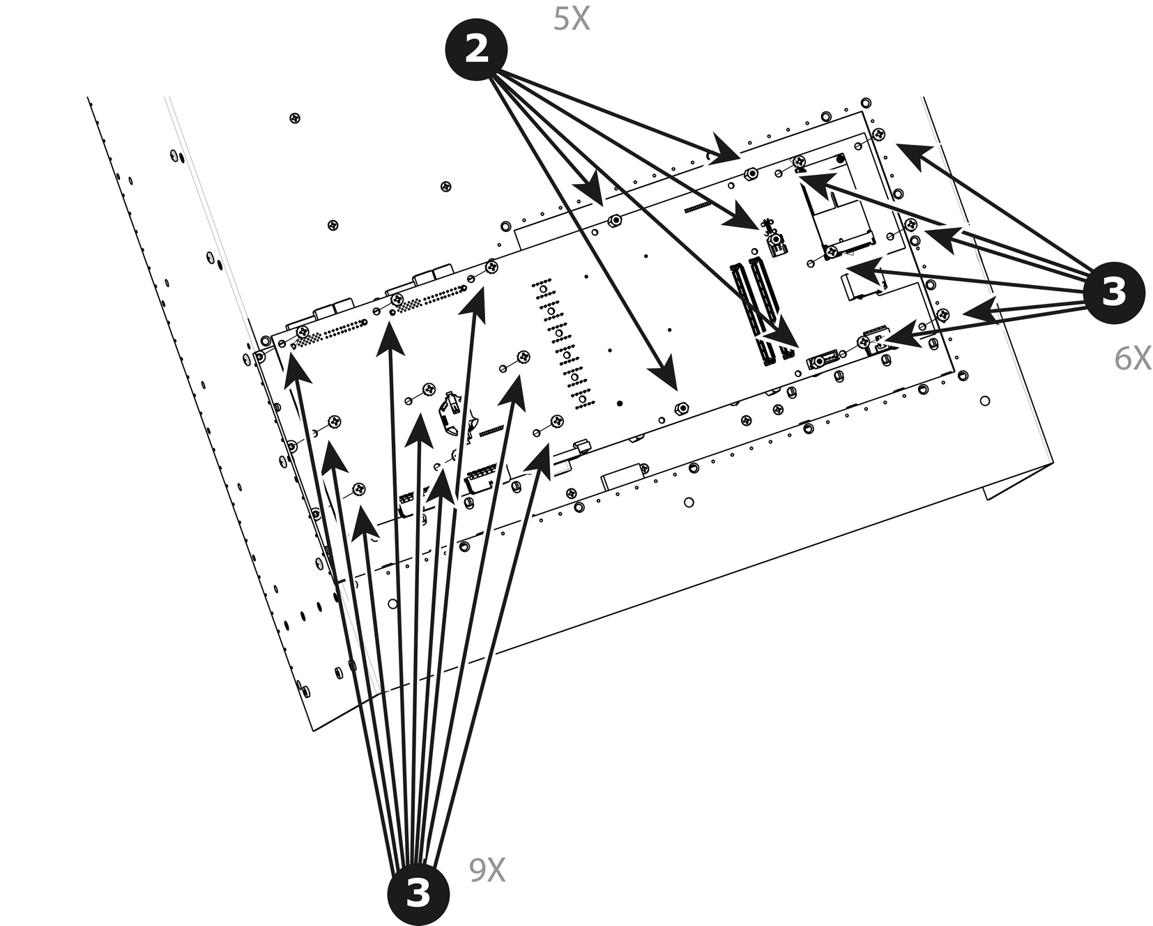
    Image 14–66
  3. Remove the 15 screws (6-32x.31 Stainless Steel) that attach the System Power Board to the Mother board.
  4. Carefully lift the board up and remove the card from the System. Don't pull the board too far because there are still 3 cables attached to the card.

    Note: Interposer card(s) may come out. In this case, re-install the boards into the motherboard slots unit.
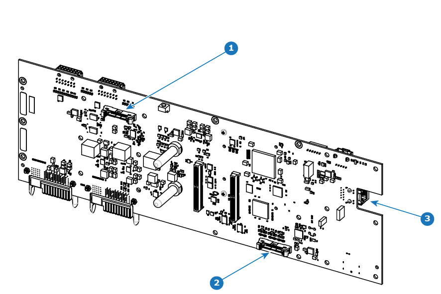
  5. Turn the board over and unplug the Genlock, Ethernet cable and Front panel keyboard cable. Refer to the drawing below (Bottom side) to locate the cables.
Note: After the system card is removed, you can also replace the System battery or the Solid-State memory. These items can be serviced without removing the System-Power board as described in other sections of this chapter.
How to install the System-Power Board

To install the System-Power Board follow the same procedure in the reverse order.
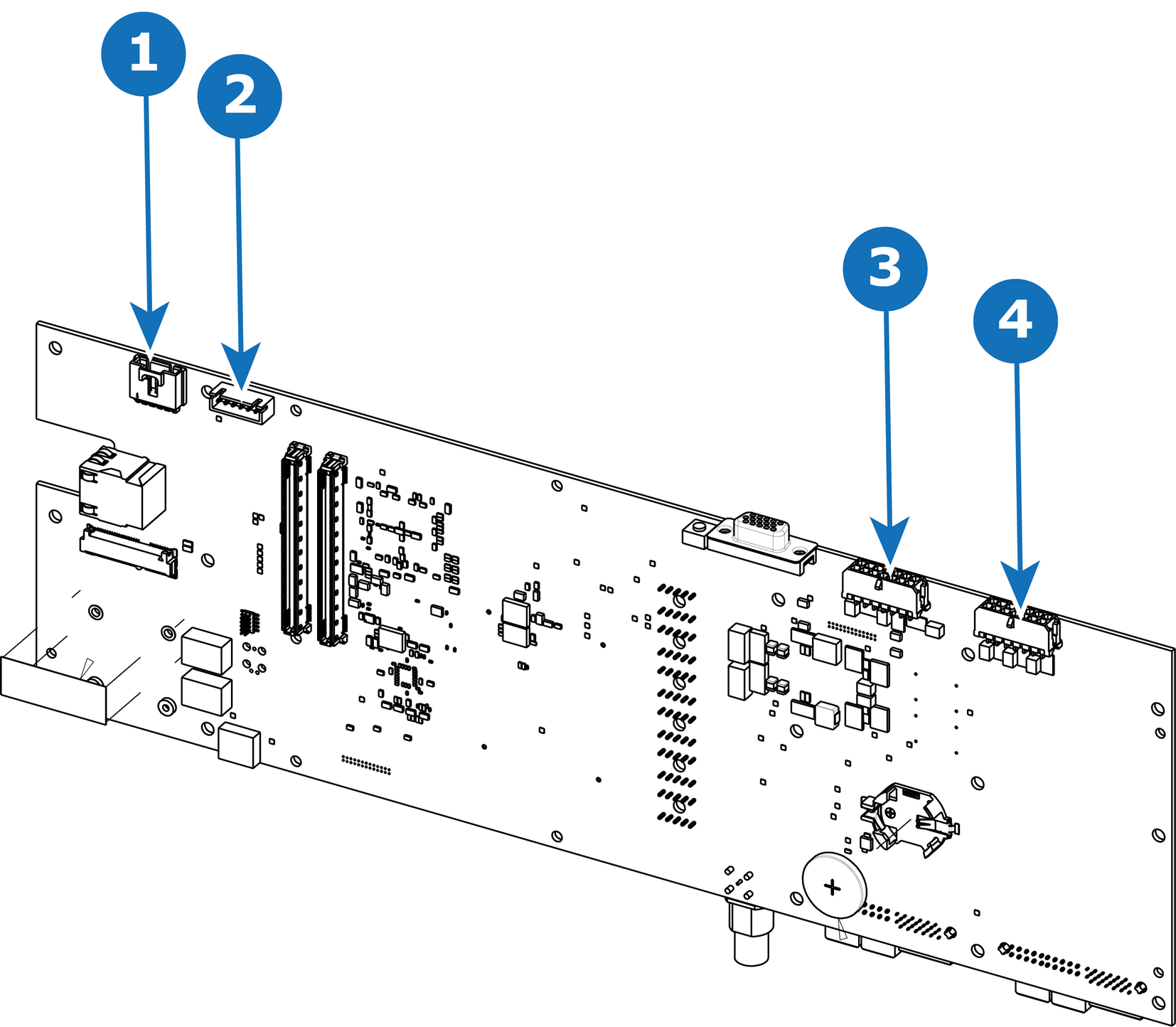
E2 Gen 1 system power board – top side
Image 14–67 E2 Gen 1 system power board – top side
1
USB connector
2
VFD connector
3
3RU connector
4
1RU connector
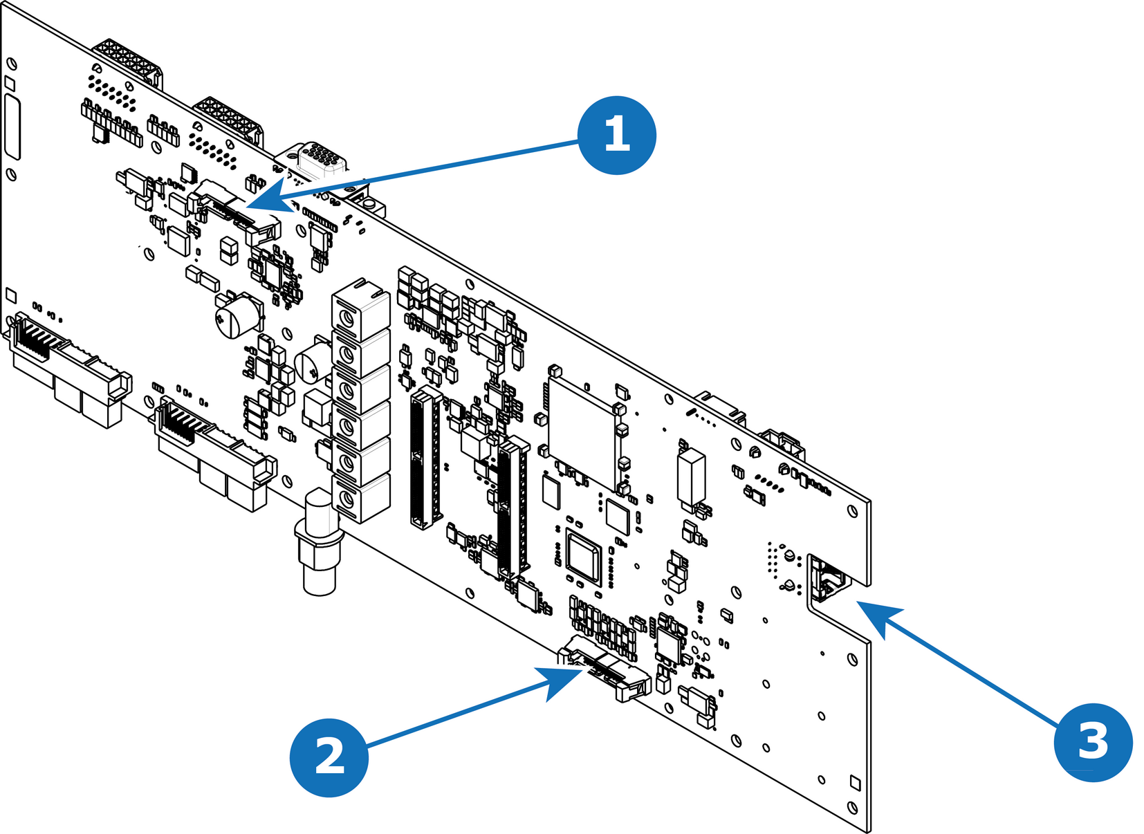
E2 Gen 1 system power board – bottom side
Image 14–68 E2 Gen 1 system power board – bottom side
1
Keyboard connector
2
Genlock connector
3
Ethernet connector
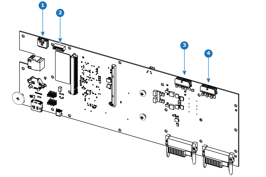
E2 Gen 2 system power board – top side
Image 14–69 E2 Gen 2 system power board – top side
1
USB connector
2
VFD connector
3
3RU connector
4
1RU connector
E2 Gen 2 system power board – bottom side
Image 14–70 E2 Gen 2 system power board – bottom side
1
Keyboard connector
2
Genlock connector
3
Ethernet connector