15.25 Power Supply Guide

Flow chart
Image 15–59
Note: Actually to remove the power supply guide, you must move the entire motherboard mount forward. The reason for this is there is not enough space to get the power supply guide out without moving everything towards the front of the chassis.
Overview
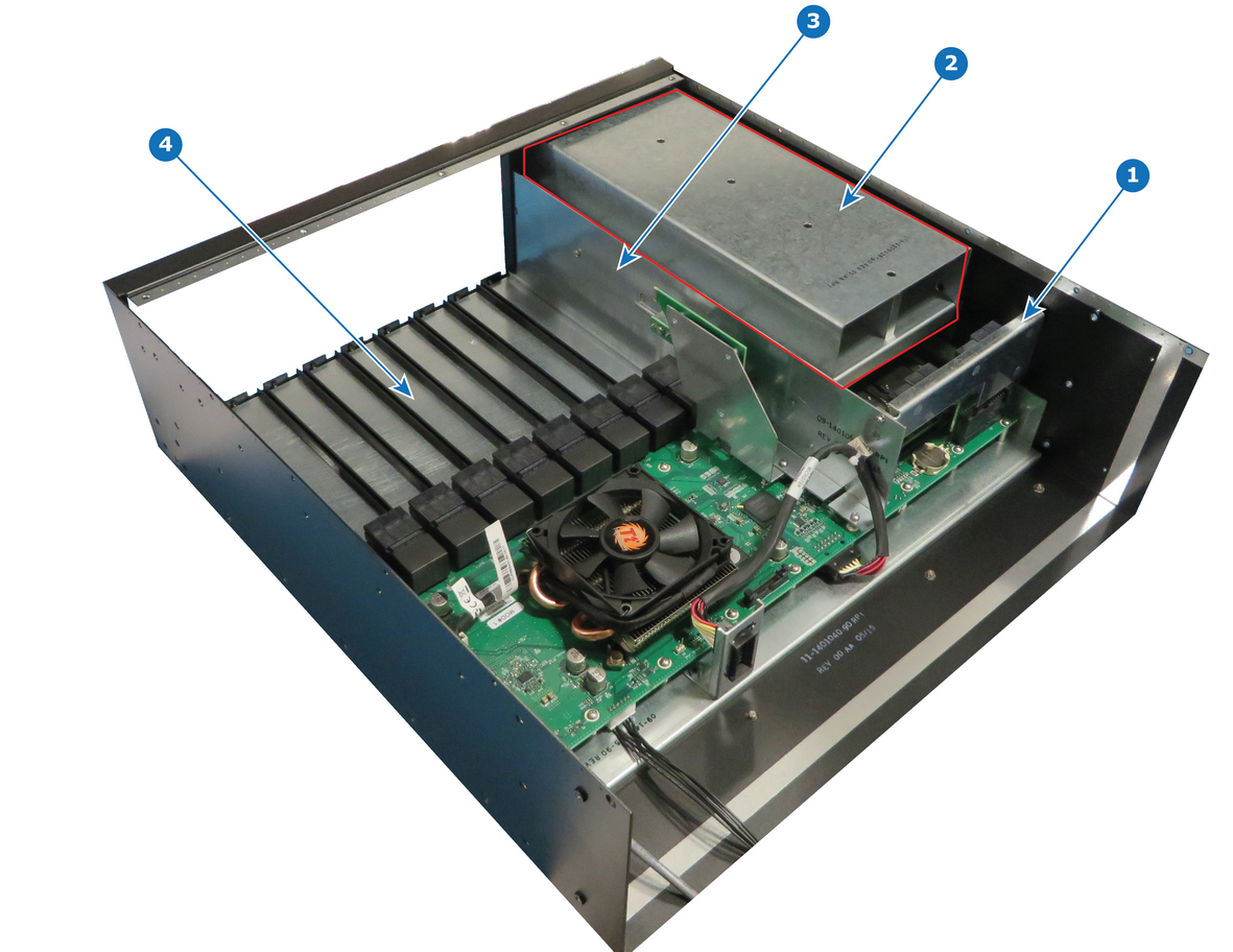
Image 15–60
1
Power Interposer
2
Power supply guide
3
Side Support Plate
4
Motherboard Mount
Necessary tools

1 x Phillips Screwdriver #2

Note: To remove the power supply guide, the entire Motherboard Mount must be move forward.
How to remove Power Supply Guide
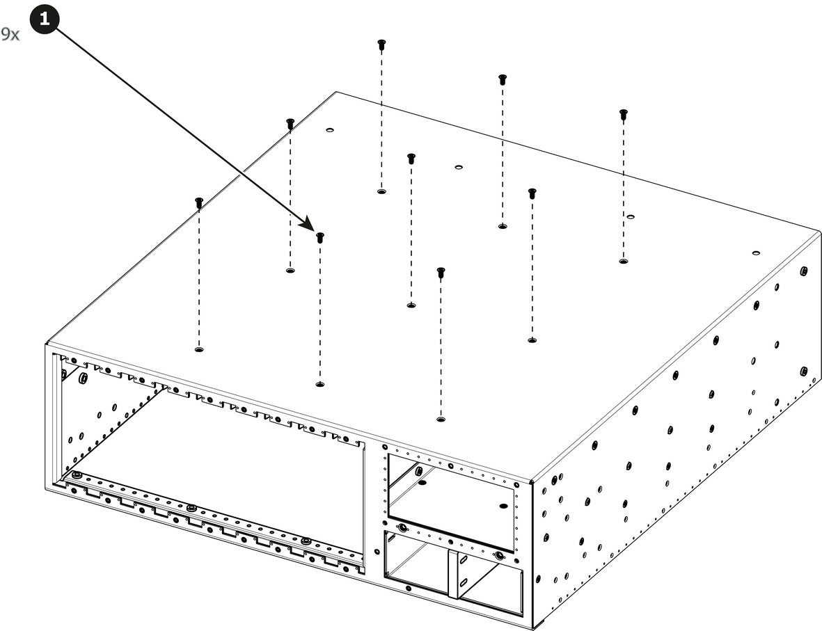
  1. Turn the unit over to remove the nine flat head screws (4-40x0.25 — black) that attach the Motherboard Mount to the bottom of the chassis.

    Image 15–61
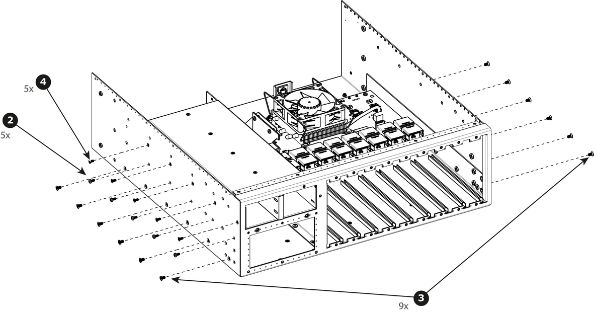
  2. Remove the five pan head screws (4-40x0.25 — black) that attach the Power supply guide to the side of the chassis.
  3. Remove the twelve flat head screws (6-32x0.25 — black) that attach the Motherboard Mount to the side of the chassis.
  4. Remove the five flat head screws (4-40x0.25 — black) that attach the Motherboard Mount to the side of the chassis.

    Image 15–62
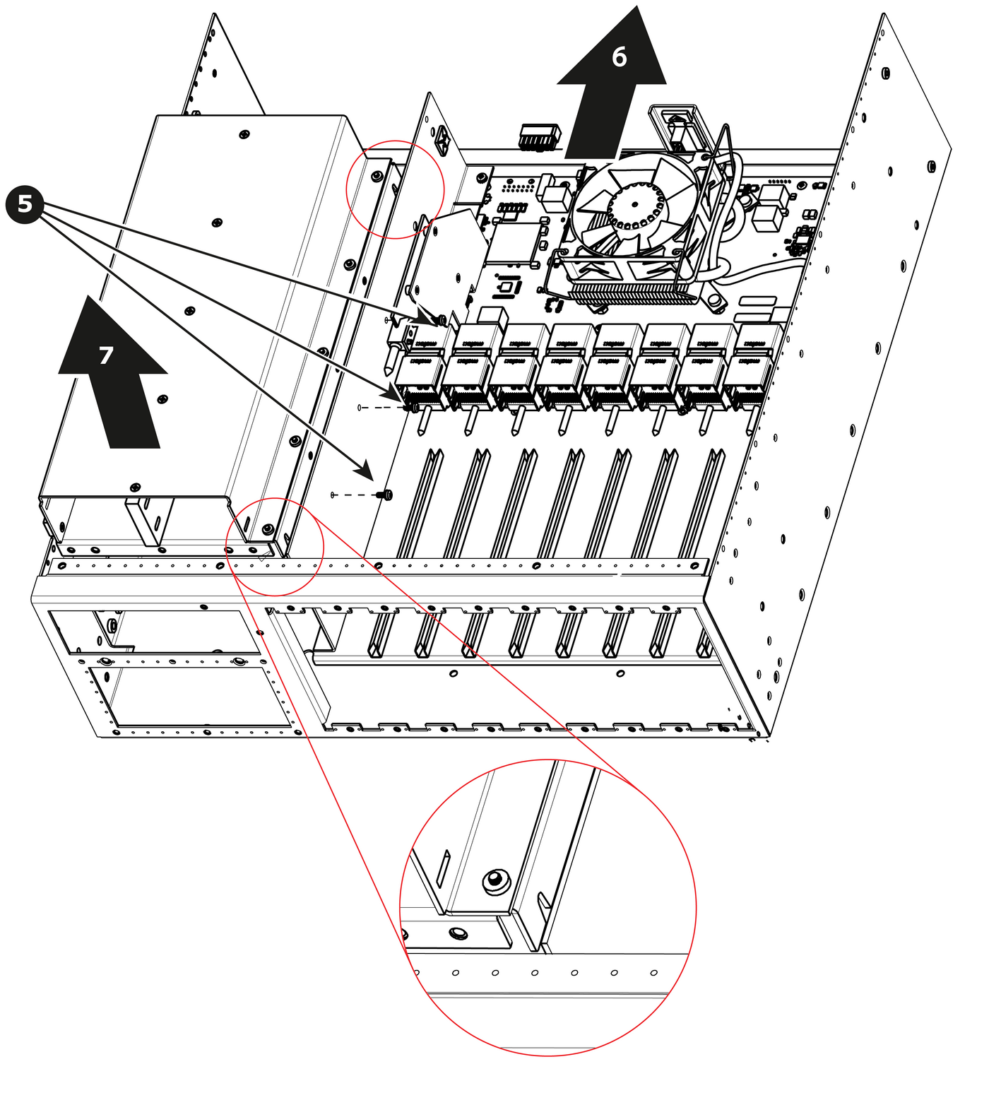
  5. Remove the three pan head screws (4-40x0.25 — Stainless steel) that attach the Power Supply Guide to the side of the side support plate.

    Image 15–63
  6. Move the entire motherboard mount forward
  7. Gently pull the Power Supply Guide away from the unit.
How to install Power Supply Guide

To install the Power Supply Guide follow the same procedure in the reverse order.

Note: There are slots cut into the bottom which will make installation of the guide much easier. See detail on the previous drawing.