7.17 Configuration Menu > MVR Outputs

General

In this procedure, you can adjust the MVR outputs of the system.

Prerequisite
Adjust MVR Output
  1. Click on the MVR tab to select the outputs that will be adjusted.

    Note: The MVR outputs have a Unit ID, which in linked chassis systems helps to identify the particular unit in the system on which MVR outputs are physically located.
(Optional) Edit the Name
  1. Double click on default name in the Name list to edit the name.
  2. When the area turns blue, click the eraser icon to clear the field.
  3. Type a new name and hit enter when done.
(Optional) Adjust Output Parameters

Select one of the MVR outputs and click on the Adjust tab that is located on the top. The output adjustment panel is divided in three sections (Main, Timing, Connector). In the Adjustment panel you can:

  1. [Main tab] Auto Configure Output Format function is not available for MVR at this time.
  2. [Main tab] Edit the name.
  3. [Main tab] Select Format value and Frame Rate.
  4. [Main tab] Enable Test Patterns with raster box and enable diagonal motion.
  5. [Timing tab] Read all timing parameters associated with the selected format and make adjustments. Adjustments are limited to the formats that can be pre-selected.
  6. [Connector tab] Select Color space and Sample bit depth available as reported from the EDID of the Device.
  7. [Connector tab] Select HDCP Mode for Multiviewer outputs.

    The default for HDCP Mode is Off. To turn On the HDCP Mode, click on the empty HDCP Mode checkbox. When the checkbox displays a check mark, HDCP Mode is On. HDCP Mode is not applicable to SDI outputs.
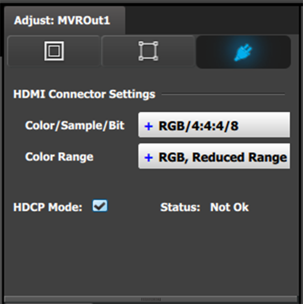
    Image 7–6 Adjust tab: Connector Settings subtab
Note: Only a few formats are available for the MVR Outputs as it is not a Program Output
Note: Any Aux destination with a frame rate that is different from the System Native Rate will not be available to add to the MVR output. More details on this topic in the Help File in your Event Master Processor.