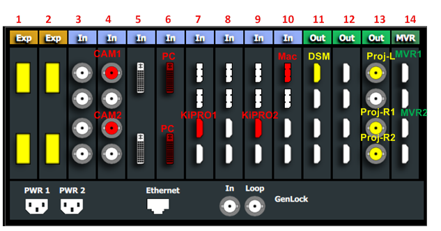
Application Diagram
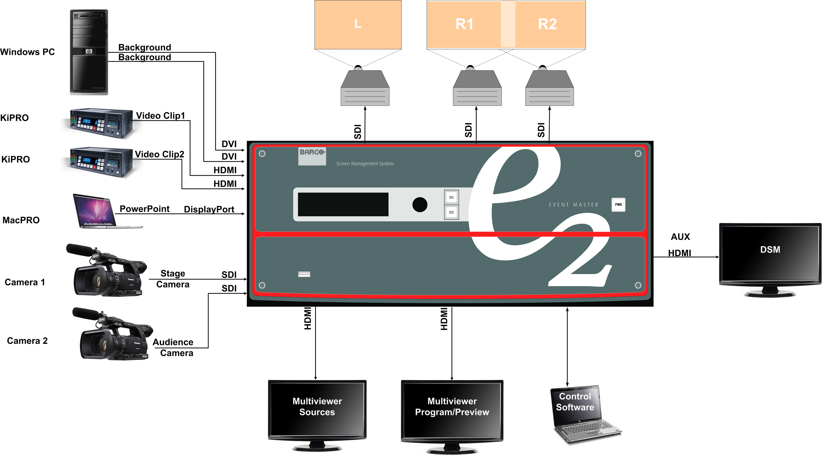

Connect the input and output devices to the E2 as follows:
| Signal Type | Device Name | Content | Connector Type | Slot-Connectors |
| Input | CAM1 | Audience camera | 3G-SDI | 4-1 |
| Input | CAM2 | Stage Camera | 3G-SDI | 4–3 |
| Input | PC | Background | DVI | 6–1 |
| Input | PC | Background | DVI | 6–2 |
| Input | KiPRO1 | Video Clip1 | HDMI | 8–3 |
| Input | KiPRO2 | Video Clip2 | HDMI | 9–3 |
| Input | MacPRO | Power Point | DisplayPort | 10–1 |
| Output (AUX) | DSM | DSM for PowerPoint | HDMI | 11–1 |
| Output | Proj-L | Projector Left Screen | SDI | 13–1 |
| Output | Proj-R1 | Projector Right Screen 1 | SDI | 13–3 |
| Output | Proj-R2 | Projector Right Screen 2 | SDI | 13–4 |
| Multiviewer | MVR1 | Program/ Preview Monitor | HDMI | 14–1 |
| Multiviewer | MVR1 | Input Sources Monitor | HDMI | 14–3 |