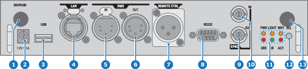
10/100 base-T for external control over IP and Art-Net
5
DMX interface input
6
DMX interface output
7
XLR input for wired projector control
8
RS232 for serial communication
9
Sync Out 3D
10
Sync In 3D
11
Status lights
12
IR receive sensor
13
Pulse 4G antenna input (optional)
Caution: Ethernet should only be connected to either the 10/100 base-T port (on the communication panel) or the HDBaseT input (on the Quad Combo Input). Using both at the same time will lead to undefined behavior.
12 V output
12 V output, maximum 1 A, available when projector is not in stand by.
DMX interface
DMX is used as communication bus between different devices in the light technic. Each device has an input and an output, so that the bus can be looped between the different devices. According the standard a five wire cable with XLR connector is used.
You can use the DMX input port to connect a DMX device (DMX console) to the projector. This way you can control the projector from that DMX device (console). The DMX output port can be connected with the next device in the loop.
DMX
Pin
Description
1
Earth
2
Cold
3
Hot
4
Return - (or not used)
5
Return + (or not used)
Note: Due to technical reasons, the DMX interface can only be used if the Pulse Quad Combo input Mk III is mounted in input slot L1.
DMX
DMX-512 Lighting protocol over RS-485 interface. Carries information of 512 channels from a lighting controller to lighting devices. Standardized by USITT.
RS232/RS422 input
The communication interface of the UDX series projector supports RS232 and RS422 serial communication on two different types of input connectors, a Sub-D connector and an USB connector acting as RS input when connected to an USB input of a PC.
You can use the RS232/RS422 input to connect a local PC to your UDX series projector. By this way you can configure and control your projector from your local PC.
Advantages of using RS232/RS422 serial communication:
easy adjustment of the projector via PC (or MAC).
allow storage of multiple projector configurations and set ups.
wide range of control possibilities.
address range from 0 to 255.
sending data to the projector (update).
copying data from the projector (backup).
RS232/422 input (Sub-D) port
Pin
Description
1
DCD : Data Carrier Detect
2
RXD- : Receive Data
3
TXD- : Transmitted Data
4
DTR : Data Terminal Ready [RS232] / TXD+ : Transmitted Data [RS422]
5
GND : Ground
6
DSR : Data Set Ready [RS232] / RXD+ : Received Data [RS422]
7
— (not connected) —
8
CTS : Clear To Send
9
RI : Ring Indicator
RS232
An Electronic Industries Association (EIA) serial digital interface standard specifying the characteristics of the communication path between two devices using either D-SUB 9 pins or D-SUB 25 pins connectors. This standard is used for relatively short-range communications and does not specify balanced control lines. RS-232 is a serial control standard with a set number of conductors, data rate, word length and type of connector to be used. The standard specifies component connection standards with regard to computer interface. It is also called RS-232-C, which is the third version of the RS-232 standard, and is functionally identical to the CCITT V.24 standard. Logical '0' is > + 3V, Logical '1' is < - 3V. The range between -3V and +3V is the transition zone.
RS422
An EIA serial digital interface standard that specifies the electrical characteristics of balanced (differential) voltage, digital interface circuits. This standard is usable over longer distances than RS-232. This signal governs the asynchronous transmission of computer data at speeds of up to 920,000 bits per second. It is also used as the serial port standard for Macintosh computers. When the difference between the 2 lines is < - 0.2V that equals with a logical '0'. When the difference is > +0.2V that equals to a logical '1'..
USB port
The communication interface is equipped with a master USB port, type “A” connector. This USB port will simplify the service procedures for firmware updates or for downloading the log files without a network connection.
If the only file on the USB device is the firmware file (a “*.fw” file), the projector will automatically start one of the following processes.
cornet<version nr>.fw: The projector will update or downgrade, depending on the version number.
LogExtractor.fw: The log files will be downloaded.
Note: Make sure that any used USB-stick is FAT32 compatible and contains no other files or folders.