
13.5 Rear I/O and VPU Heatsink Fan
Flow chart
 Image 13–6
 Overview
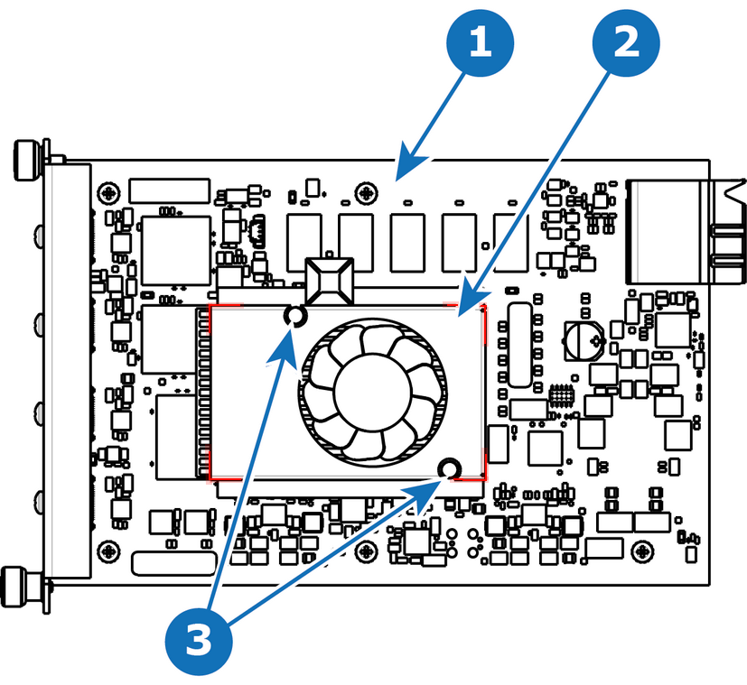 Image 13–7
 - 1
- I/O board
- 2
- Heatsink Fan
- 3
- Pins
Concerned parts
Necessary tools
- 1 x Phillips Screwdriver #2.
- Small fine nose pliers.
How to remove the Rear I/O or VPU card heatsink fan
- After you remove the card from the chassis, unplug the heatsink fan power wire from the PCB connector.
- Locate the two pins that are located on opposite corners of the Heatsink and secure the fan on to the board.
- Turn the board over and with small fine nose pliers while bringing together the two sides of the pin push it through the hole.
- After both pins are pushed through the holes, you can remove the heatsink from the card.
How to install the Rear I/O or VPU card heatsink fan
- Remove the heatsink with the fan from the package.
- Remove the plastic cover from the bottom of the fan to expose the adhesive material.
- Align the holes in the board with the pins of the Heatsink.
- Press firmly the heatsink to the devices below.
- Plug the heatsink fan power wire to the PCB connector.