A.4 Standard connector pinouts
DisplayPort connector pinouts
The following figure illustrates the DisplayPort connector.
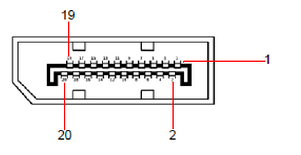 Image A–1 DisplayPort connector
The following table lists the DisplayPort connector pinouts.
| DisplayPort connector |
| Pin | Signal | Pin | Signal |
| 1 | ML_Lane 0 (p) | 11 | GND |
| 2 | GND | 12 | ML-Lane 3 (n) |
| 3 | ML_Lane 0 (n) | 13 | CONFIG1 (connected to Ground) |
| 4 | ML-Lane 1 (p) | 14 | Config2 (connected to Ground) |
| 5 | GND | 15 | AUX CH (p) |
| 6 | ML_Lane 1 (n) | 16 | GND |
| 7 | ML-Lane 2 (p) | 17 | AUX CH (n) |
| 8 | GND | 18 | Hot Plug Detect |
| 9 | ML_Lane 2 (n) | 19 | Return (return for power) |
| 10 | ML_Lane 3 (p) | 20 | DP_PWR Power for connector (3.3 V, 500 mA) |
DVI connector pinouts
The following figure illustrates the DVI connector.
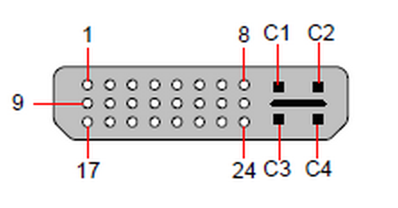 Image A–2 DVI connector
The following tables lists DVI Connector pinouts. Please note:
- T.M.D.S = Transition Minimized Differential Signal
- DDC = Display Data Channel
| DVI connector |
| Pin | Signal | | |
| 1 | T.M.D.S. Data 2- | 13 | T.M.D.S. Data 3+ |
| 2 | T.M.D.S. Data 2+ | 14 | +5V Power |
| 3 | T.M.D.S. Data 2/4 Shield | 15 | ground (for +5V) |
| 4 | T.M.D.S. Data 4- | 16 | Hot Plug Detect |
| 5 | T.M.D.S. Data 4+ | 17 | T.M.D.S. Data 0- |
| 6 | DDC Clock | 18 | T.M.D.S. Data 0+ |
| 7 | DDC Data | 19 | T.M.D.S. Data 0/5 Shield |
| 8 | Analog Vertical Sync | 20 | T.M.D.S. Data 5- |
| 9 | T.M.D.S. Data 1- | 21 | T.M.D.S. Data 5+ |
| 10 | T.M.D.S. Data 1+ | 22 | T.M.D.S. Clock Shield |
| 11 | T.M.D.S. Data 1/3 Shield | 23 | T.M.D.S. Clock + |
| 12 | T.M.D.S. Data 3- | 24 | T.M.D.S. Clock - |
| MicroCross Pins |
| Pin | Signal | Pin | Signal |
| C1 | Analog Red Video | C4 | Analog Horizontal Sync |
| C2 | Analog Green Video | C5 | Analog Common Ground Return |
| C3 | Analog Blue Video | | |
Ethernet connector pinouts
The following figure illustrates the Ethernet connector.
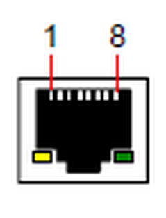 Image A–3 Ethernet connector
The following table lists Ethernet connector pinouts.
| | | | 10/100 Base-T — RJ45 port | 1000 Base-T — RJ45 port |
| Pin | Pair | Color | Description | Description |
| 1 | 3 | white/green | TXD+ | TX0+ |
| 2 | 3 | green | TXD- | TX0- |
| 3 | 2 | white/orange | RXD+ | RX0+ |
| 4 | 1 | blue | — | TX1+ |
| 5 | 1 | white/blue | — | TX1- |
| 6 | 2 | orange | RXD- | RX0- |
| 7 | 4 | white/brown | — | Rx1+ |
| 8 | 4 | brown | — | RX1- |
HDMI connector pinouts
The following figure illustrates the HDMI connector.
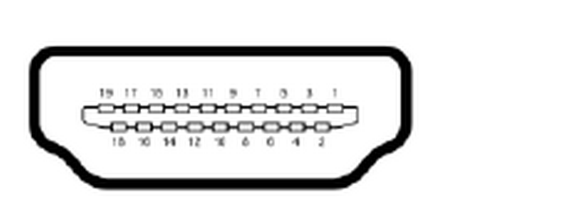 Image A–4 HDMI connector
The following table lists HDMI connector pinouts.
| HDMI connector |
| Pin | Signal | Pin | Signal |
| 1 | TMDS Data2+ | 11 | TMDS Clock Shield |
| 2 | TMDS Data2 Shield | 12 | TMDS Clock- |
| 3 | TMDS Data2- | 13 | CEC |
| 4 | TMDS Data1+ | 14 | |
| 5 | TMDS Data1 Shield | 15 | SCL |
| 6 | TMDS Data1- | 16 | SDA |
| 7 | TMDS Data0+ | 17 | DDC/CEC/HEC Ground |
| 8 | TMDS Data0 Shield | 18 | +5 v Power (max 50 mA) |
| 9 | TMDS Data0- | 19 | Hot Plug Detect (All Versions) and HEC Data+ |
| 10 | TMDS Clock+ | | |