13.6 Tri-Combo Input Card Disassembly and Assembly

Flow chart
Image 13–8 TCI cards
Concerned parts
R9009401Tri-Combo Input
R767263KFansink kit
Required tools

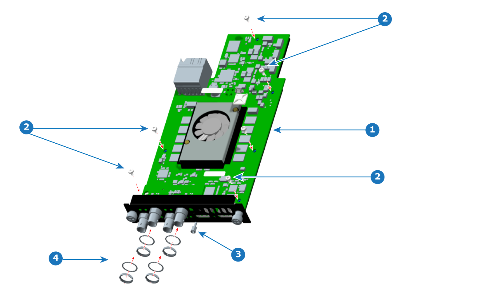
Phillips screwdriver PH2

How to disassemble a Tri-Combo Input (TCI) card
  1. Cut the zip tie that secures the fan cable, and remove the fan cable.

    Image 13–9 Screws, standoff, washers, and nuts
    1
    PCBA (on mounting bracket)
    2
    Screws
    3
    Standoff
    4
    BNC washers and nuts
  2. Remove the six screws that secure the PCBA to the mounting bracket.
  3. Remove the BNC nuts and washers.
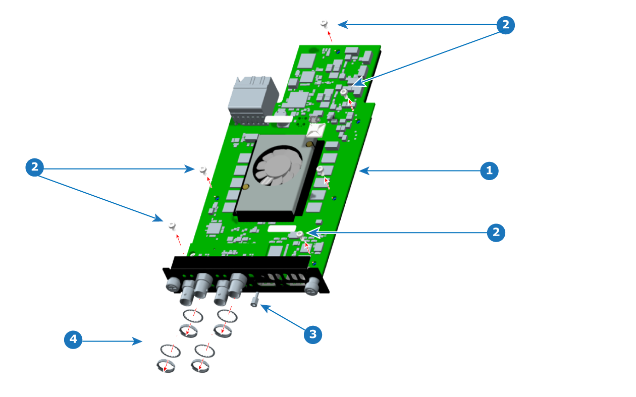
  4. Loosen and remove the standoff.

    Image 13–10 PCBA and mounting bracket
    1
    PCBA (with mezzanine and fansink installed)
    2
    Mounting bracket
  5. Remove the PCBA from the sheet metal bracket.

    Image 13–11 Mezzanine removal
    1
    PCBA (with fansink installed)
    2
    Mezzanine
    3
    Mezzanine BNC connectors
    4
    Mainboard BNC connectors
  6. Remove the mezzanine.
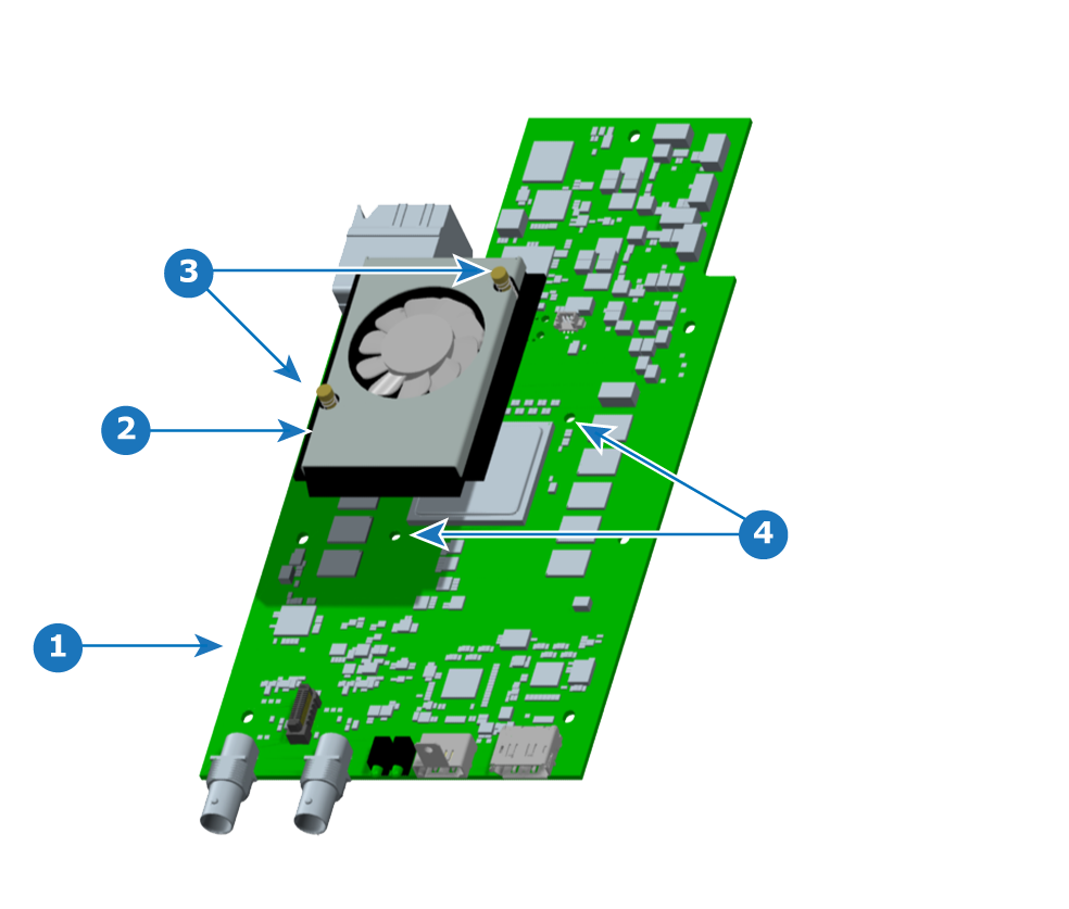
  7. Remove the fansink (heatsink fan), if necessary.

    Turn over the PCBA and push the fansink pins. (The fansink pins will not come free of the fansink.)

    Image 13–12 TCI card fansink pin locations
    1
    Fansink pins
Caution: Do not reuse a fansink, once it has been removed from the mainboard (PCBA). The thermal compound will no longer be properly located, and the compression of the pins during removal will prevent them from fastening properly to the motherboard. Use the fansink replacement kit.
How to assemble a Tri-Combo Input (TCI) card
  1. Install the fansink (heatsink fan) on the main board (PCBA), if the fansink is not already present.

    1. Align the fansink pins with the holes on the PCBA.
    2. Seat the pins so that they are flush with the top of the fansink.
    3. Install the fan connector (not shown) to the connector on the PCBA.
    4. Turn the card over and spread the fansink pins—using a small, flat-bladed screwdriver—to ensure that the fansink stays attached to the card.
    Image 13–13 Fansink installation
    1
    PCBA
    2
    Fansink (heatsink fan)
    3
    Fansink pins
    4
    Pin holes
    Image 13–14 Mezzanine installation
    1
    PCBA (with fansink installed)
    2
    Mezzanine
    3
    Mezzanine BNC connectors
    4
    Mainboard BNC connectors
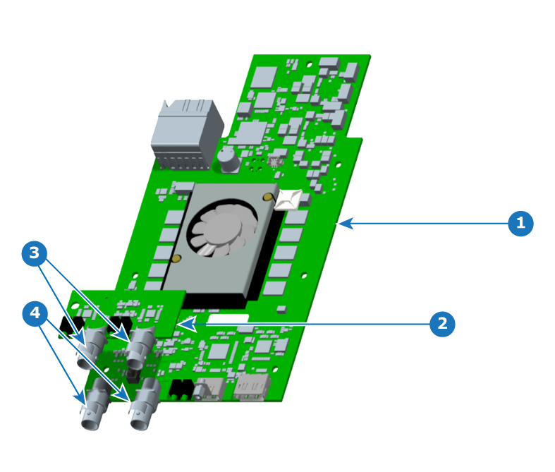
  2. Place kapton tape on the rear portion of the mainboard BNC connectors.

    (Kapton tape is not needed on the mezzanine BNC connectors.)

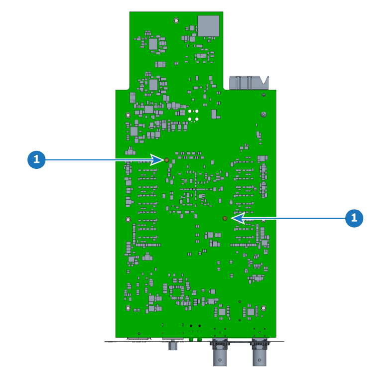
  3. Install the mezzanine on the PCBA.

    On the TCI card, make sure that the LED's length is a maximum of 1.2 mm below the bottom surface of the PCBA.

    Image 13–15 PCBA and mounting bracket
    1
    PCBA (with mezzanine and fansink installed)
    2
    Mounting bracket
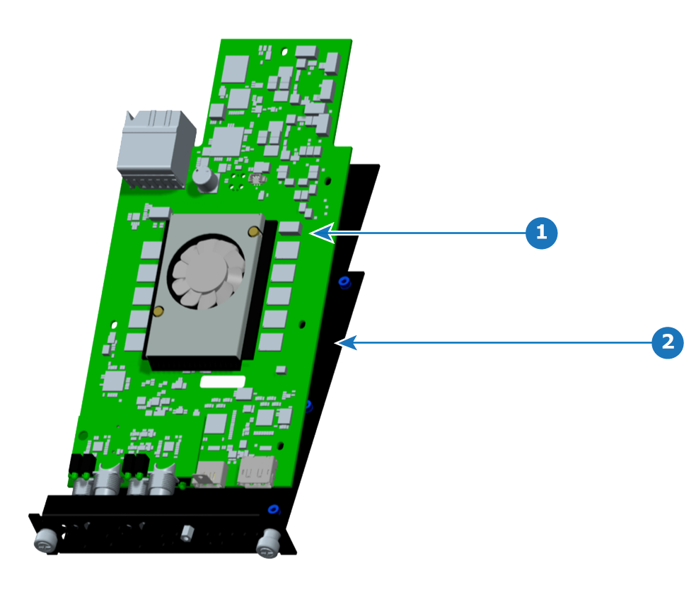
  4. Place the PCBA on the sheet metal bracket, aligning the screw holes of the PCBA with the screw holes of the bracket.

    Image 13–16 Screws, standoff, washers, and nuts
    1
    PCBA (on mounting bracket)
    2
    Screws
    3
    Standoff
    4
    BNC washers and nuts
  5. Install the six screws, but leave them loose.
  6. Install the standoff through the front plate of the bracket.
  7. Install the BNC washers and nuts.
  8. Tighten the standoff to 5 in-lbs.
  9. Tighten the BNC nuts to 12 in-lbs.
  10. Tighten the six screws to 5 in-lbs.
  11. Install the zip-tie mount and the zip tie.
  12. Secure the fan cable with the zip tie.