13.24 USB Cable

Flow chart
Image 13–67
Note: The USB cable is connected to the USB extension cable (the cable that is connected to the System-Power board). This procedure provides instructions how to disconnect it from both sides of the cable.
Concerned parts
R767269KCable Kit Set
Necessary tools
How to remove the USB cable
  1. Completely detach and pull the Front Cover assembly away from the unit (refer to the related procedure).
  2. Disconnect the USB cable from the USB Extension cable (the other side of the cable is connected to the System-Power board).
  3. Disconnect the VFD and Front Keyboard Panel cables from the VFD assembly and Front panel boards.
  4. Place the Front panel enclosure face down on a flat area.
  5. Use the nut socket to remove the 16 nuts (6-32) that attach the first plate to the assembly.
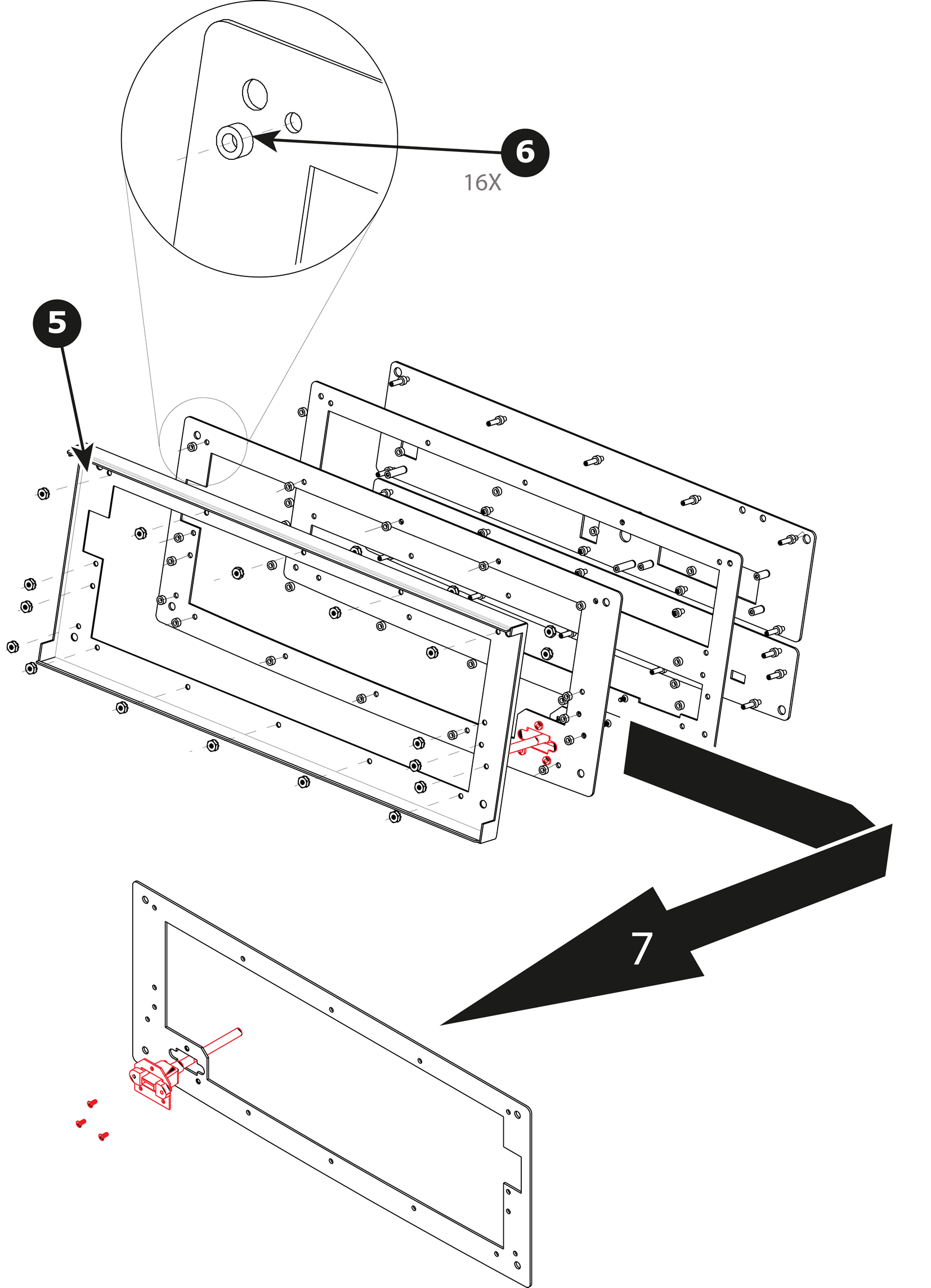
  6. Remove and put aside the 16 spacers situated under the plate you just removed.

    Image 13–68
  7. Remove the plate that has been exposed after the nuts are removed.
  8. Remove the three screws that hold the USB cable into the metal plate.

    Image 13–69
  9. Remove the USB cable.
How to install the USB cable

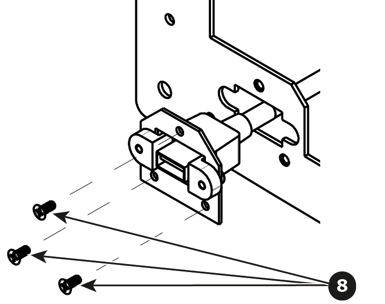
To install the USB cable follow the same procedure in the reverse order.