General
Output configurations that are created in the previous menus are assigned to destination in the Destination Panel.
Output configurations that are created in the previous menus are assigned to destination in the Destination Panel.
Destination configuration menu is accessed by clicking on the Destination tab.
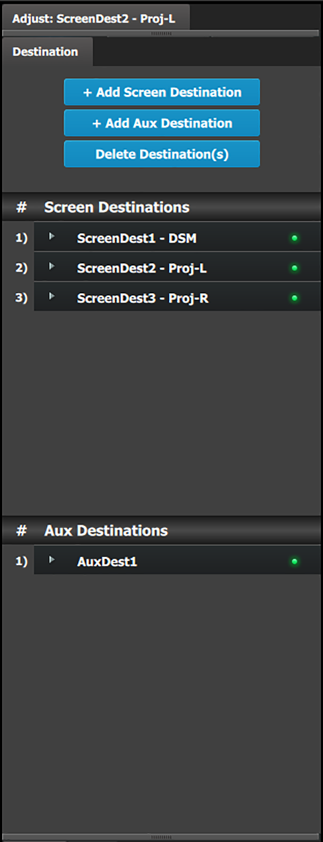 | This menu provides:
|
The user can assign Outputs to Output configurations—manually or automatically—and delete Outputs from Output configurations.
A few words about destination formats:
The following rules apply when defining a Screen / AUX Destination configuration:
Destinations accept only the same Output connector types.
SDI and HDMI connectors cannot be mixed in the same destination.
Destinations accept Output configurations only with the same number of Output connectors.
Output configurations with a different number of connectors cannot be combined. For example if the first Output configuration added is an HDMI output configuration with two (2) connectors (grouped connector), an HDMI output configuration with one (1) connector cannot be added to the same destination.
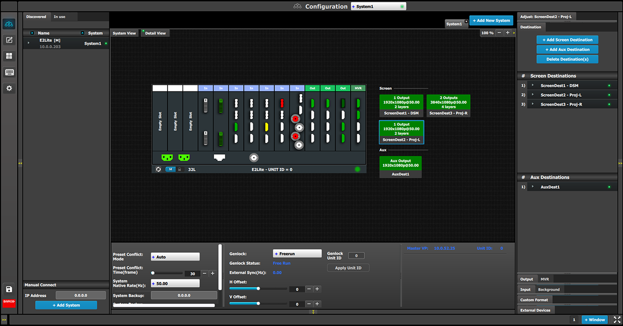
Screen Destinations and AUX Destinations are represented graphically in the Diagram area.
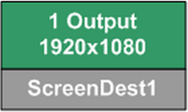 | Green: Output(s) have been assigned to the destination |
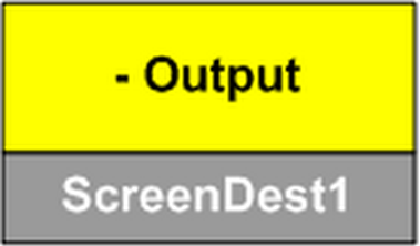 | Yellow: Output(s) have not been assigned to the destination. |
It is possible that after the unit is turned on, the hardware configuration can be altered making certain Destinations to have invalid Output configurations.
In this case the Destination in the System Diagram becomes grey and adjustment are disabled. In this case the destination needs to be deleted and new one created to reflect the existing output configuration.
Use the Programming menu to manipulate Screen Destinations.
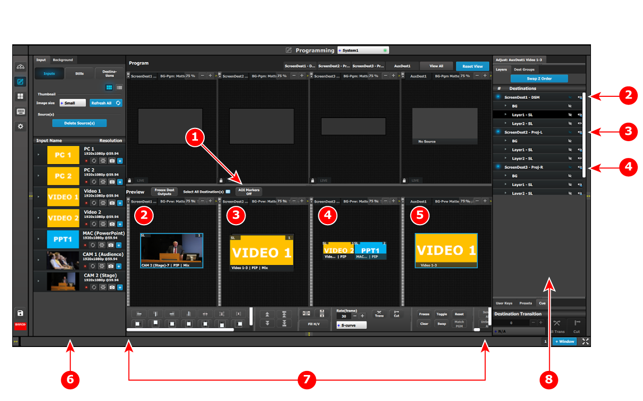
Set the AOI Markers to “Off.”
Turning on the AOI Markers "On" or "Off" affects how the system-wide functions (the Layer alignment buttons, including Fill H, Fill V and Fill H/V) work. With the AOI Markers set to "On," the Layer alignment buttons align the Layer into the Screen Destination in which the center of the Layer is located. With the AOI Markers set to "Off," the Layer alignment buttons align the Layer in the entire Screen Destination.
Apply system-wide functions, User Keys, or Presets to Layers in the Screen Destinations.
Based on the Aux Capacity, the user can create AUX Destination on an output card. The AUX capacity defines the Input capacity and scaler size of the AUX.
All output cards can be Auxes while only any 2 output cards with a total of 8 outputs can be Program outputs
| Aux Capacity | Number of Outputs | Max output Resolution |
| 2K (Single Link) | 4 | 1920x1200 |
| Dual Link | 2 | 1920x1200 |
| 4K | 1 | 1920x1200 |
| 8L | 1 | 1920x1200 |
Use the Programming menu to manipulate AUX Destinations.