In this procedure, you will add Outputs to the system .
Prerequisite
Ensure that you are familiar with the Configuration Menu. For details on this menu, please refer to chapter “Configuration Menu”
Note: If more than one Output is utilized, repeat the below steps until all inputs are added and adjusted.
(Optional) Auto create Outputs
If the Auto create Outputs is pressed, then the software will add all unassigned outputs to the output list and number them sequentially.
This button is a shortcut for systems utilizing a large number of outputs.
(Optional) Edit the Name
Once all connectors are added they appear in a list directly under the Output Tab. It is recommended to name outputs based on the actual connection scenario instead of the connected devices function. This is due to several layers of naming that can be done in the system to simplify understanding during operation.
Double click on default name in the Name list to edit the name.
When the area turns blue, click the eraser icon to clear the field.
Type a new name.
Add Output
Click on the Output tab to select the outputs that will be defined.
Click on the +Add Output blue button to enter the Add mode.
Click on the Done Adding button to exit the Add mode.
(Optional) Delete Outputs
Click on the blue button Delete Output(s).
From the Name list click on the “x” space next to the Output(s) you wish to delete. Or select the connector.
Hit the red button Delete Output(s) button. All of the selected Outputs will be removed from the list.
(Optional) Adjust Output Parameters
Click on the Adjust tab that is located on the top. The output adjustment panel is divided in three sections (Main, Timing, Connector). In the Adjustment panel you can:
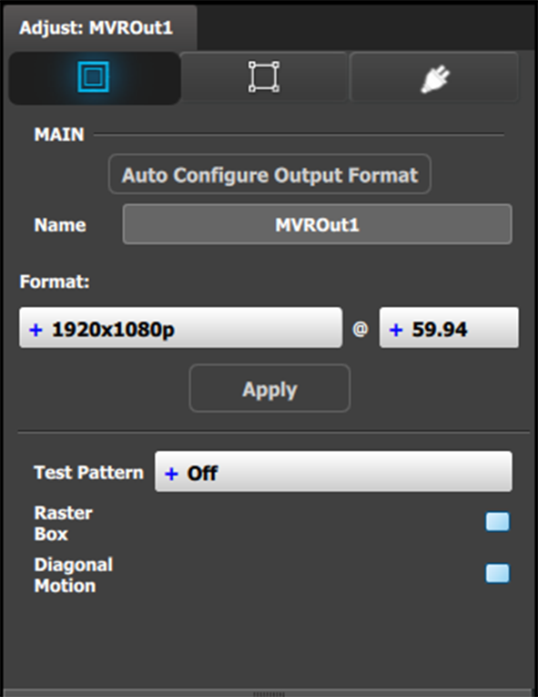
[Main tab] Edit the name.
[Main tab] Select Format value and Frame Rate.
[Main tab] Enable Test Patterns with raster box and enable diagonal motion.
[Main tab] Define the Area of interest (AOI).
Image 7–1Adjust MVR panel—Main
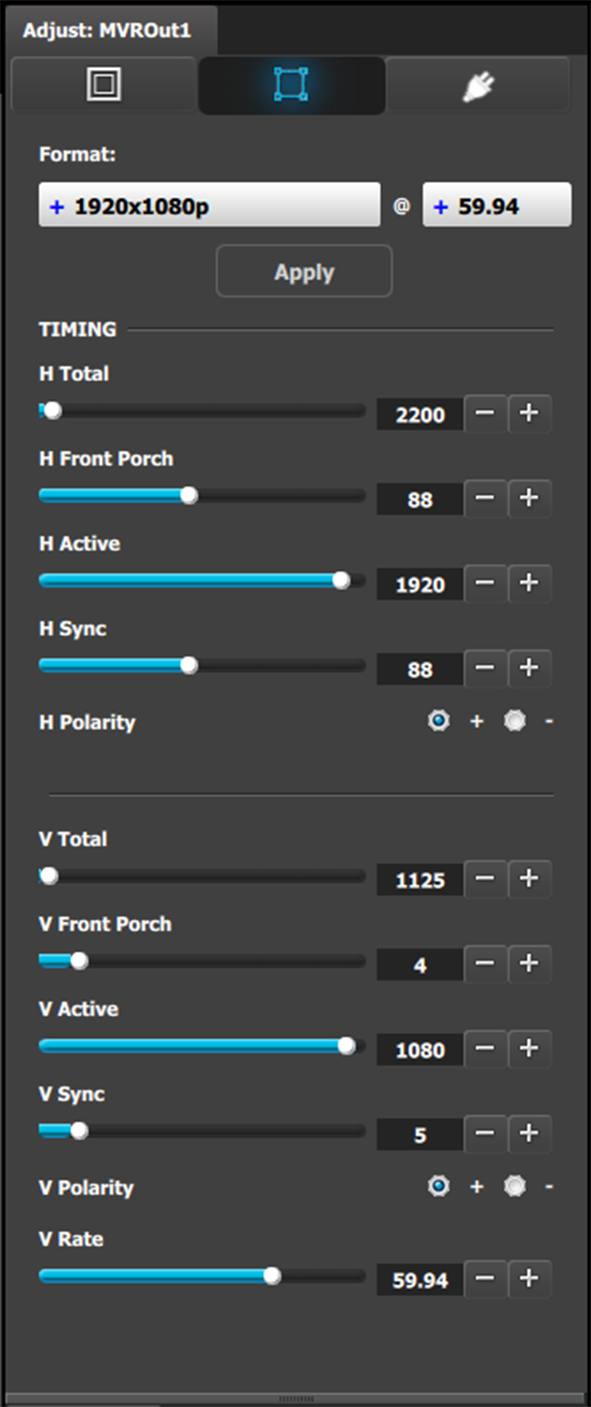
[Timing tab] Read all timing parameters associated with the selected format and make adjustments.
Image 7–2Adjust MVR panel—Timing
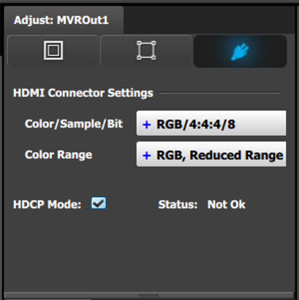
[Connector tab] Select SDI type and Sync standards.
[Connector tab] Select Color space and Sample bit depth available as reported from the EDID of the Device.
[Connector tab] Change Connector capacity as long as the connector is not included in a Destination.
[Connector tab] Select HDCP Mode On or Off.
The default for HDMI outputs is Off. To turn On the HDCP Mode, click on the empty checkbox. When the checkbox displays a check mark, HDCP Mode is On. HDCP Mode is not applicable to SDI outputs.