1.3 Product overview

Overview
Image 1–1
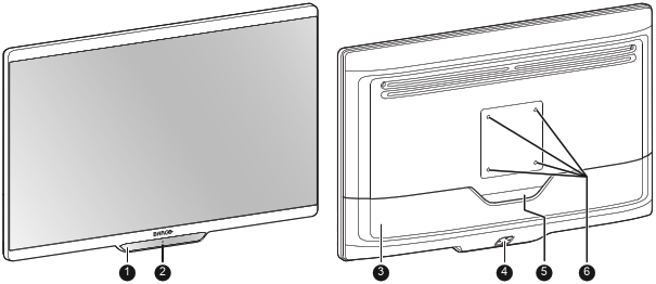
  1. 5-key capacitive front keyboard

    By default only the stand-by key ( ) is visible. For keyboard activation please refer to “Front keyboard locking/unlocking

  2. Stand-by key and power status LED (see “Power status LED ” for the behavior and different colors of the power status LED)
  3. Connector compartment cover
  4. Rear keyboard
  5. Cable routing cutout
  6. VESA mount screw holes (100 x 100 mm)
Connections – MDSC-8427 LED version
Image 1–2
  1. SDI in (*)
  2. SDI out (*)
  3. +5 VDC – 2 A power out
  4. USB 2.0 type A interface
  5. USB 2.0 type B interface
  6. Main (Right) DisplayPort in
  7. DVI-D in
  8. DVI-D out
  9. Potential Equalization pin (POAG)
  10. 2nd (Left) DisplayPort in
  11. VDC in
  12. HDMI 2 in
  13. HDMI 1 in

(*) The BNC SDI connectors match the characteristic impedance of 75 ohm cables.

Connections – MDSC-8427 12G version
Image 1–3
  1. SDI 1: Single link in or Quad link in top left (*)
  2. SDI 2: Single link out or Quad link in top right (*)
  3. SDI 3: Single link in or Quad link in bottom right (*)
  4. SDI 4: Single link out or Quad link in bottom left (*)
  5. +5 VDC – 2 A power out
  6. USB 2.0 type A interface
  7. USB 2.0 type B interface
  8. Main (Right) DisplayPort in
  9. DVI-D in
  10. DVI-D out
  11. Potential Equalization pin (POAG)
  12. 2nd (Left) DisplayPort in
  13. VDC in
  14. HDMI 2 in
  15. HDMI 1 in

(*) The BNC SDI connectors match the characteristic impedance of 75 ohm cables. See “SDI config” about the possible SDI configuration modes.