Overview
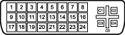
- D2_Rx- (T.M.D.S.)
- D2_Rx+ (T.M.D.S.)
- GND (data 2 shield)
- Not connected
- Not connected
- SCL (for DDC)
- SDA (for DDC)
- Not connected
- D1_Rx- (T.M.D.S.)
- D1_Rx+ (T.M.D.S.)
- GND (data 1 shield)
- Not connected
- Not connected
- +5V output (*)
- GND (cable sense)
- Hot plug detect (*)
- D0_Rx- (T.M.D.S.)
- D0_Rx+ (T.M.D.S.)
- GND (data 0 shield)
- Not connected
- Not connected
- GND (clock shield)
- CK_Rx+ (T.M.D.S.)
- CK_Rx- (T.M.D.S.)
(*) +5 VDC output selectable on either pin 14 or 16 via the OSD menu. (+5V ± 10% @ 500mA (max))