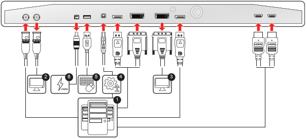
To connect the interfaces
- Connect one or more video source(s) to the corresponding video inputs of the display. For a list of supported video inputs, see “Technical specifications”.
- When the SDI video input is connected, an additional SDI video sink can be connected to the SDI output (= SDI input loop-through).
- Screen image clone: The entire active image on the screen (including OSD) can be duplicated to a FHD (1080p/1080i) signal on the DVI output connector, to which an additional DVI video sink can be connected.
- Connect the USB2.0 type B interface with a workstation to use the remote control protocol, to update the display firmware, or to be able to connect any USB peripheral with the USB interfaces of the display (see next step).
- Use any USB peripheral (keyboard, mouse, webcam, ...) by connecting it to the USB interface.
- Connector +5 VDC - 2A power out for accessory (Mating connector HIROSE RP34L-5PA- 2SC(1857)(71)).