5.3 Boresight (Scheimpflug) adjustment

What is Boresight (Scheimpflug)

The lens holder has to be adjusted so that the “sharp focus plane” of the projected image falls together with the plane of the screen (Fp1→Fp2). This is achieved by changing the distance between the DMD plane and the lens plane (Lp1→Lp2). The closer the lens plane comes to the DMD plane the further the sharp focus plane will be. It can occur that you won't be able to get a complete focused image on the screen due to a tilt (or swing) of the lens plane with respect to the DMD plane. This is also known as Scheimpflug's law. To solve this the lens plane must be placed parallel with the DMD plane. This can be achieved by turning the lens holder to remove the tilt (or swing) between lens plane and DMD plane (Lp3→Lp4).
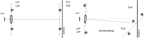
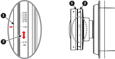
Image 5–3 Boresight (Scheimpflug) principle
Required tools
Preparations
  1. Choose the test pattern of the OSD. Switch to full screen mode.
  2. Prepare the test area. Verify that the throw ratio of the installed lens matches the requirements of the installation area (projection distance and screen size).
  3. Check that the lens is correctly installed.
  4. Zoom the lens to its widest opening (maximum image size on the screen).
  5. Adjust the focus control to search for the best sharpness of the projected image
  6. Is this a lens with an floating ring? E.g., G lens (0.65 - 0.75 : 1)[5].

    • If yes, adjust the floating ring of the lens (see next chapter).
Adjust floating ring G lens (0.65 - 0.75 : 1)[5]
Image 5–4
1
Fixed ring
2
Floating ring

Example:

When the distance between screen and projector lens is 1.4 meter, adjust floating ring scale to “1.40” to have better performance.

Note: Special Boresight tools required for G lens (0.65 - 0.75 : 1)[5]. Tools are included in the box of the lens.

Boresight extenders (with red rubber ring), 3 pieces.

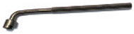
Boresight L shape socket tool.

Adjust Boresight
  1. Is this a lens with an floating ring? E.g., G lens (0.65 - 0.75 : 1)[5].

    • If yes, install the 3 Boresight extenders on the screws ① , ② and ③.
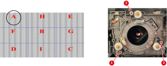
  2. If zone C is in focus on the screen, please check the focal plane of zone A.

    • If clear position is just on the screen→ No need to adjust.
    • If clear position is out of the screen(close to projector), rotate screw ① CCW and then screw ②&③ CW for half amount that① rotated. → repeat until both A and C are clear. (e.g. turning ① CCW in a circle, then turn ②&③ CW in half circle).
    • If clear position is in the screen(far from projector), rotate screw ① CW and then screw ②&③ CCW for half amount that① rotated. → repeat until both A and C are clear.
    Image 5–5
    Note: This process may cause the other areas of the image to slide out of focus. This is totally normal.
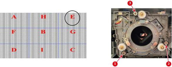
  3. If zone D is in focus on the screen, please check the focal plane of zone E.

    • If clear position is just on the screen→ No need to adjust.
    • If clear position is out of the screen(cloe to projector), rotate screw ② CCW and then screw ① &③ CW for half amount that ② rotated. → repeat until both D and E are clear. (e.g. turning ② CCW in a circle, then turn ① &③ CW in half circle)
    • If clear position is in the screen(far from projector), rotate screw ② CW and then screw ① &③ CCW for half amount that ② rotated. → repeat until both D and E are clear.
    Image 5–6
    Note: This process may cause the other areas of the image to slide out of focus. This is totally normal.
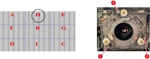
  4. If zone H is in focus on the screen, please check the focal plane of zone I.

    • If clear position is just on the screen→ No need to adjust.
    • If clear position is out of the screen(cloe to projector), rotate screw ③ CCW and then screw ① & ② CW for half amount that ③ rotated. → repeat until both H and I are clear. (e.g. turning ③ CCW in a circle, then turn ① & ② CW in half circle).
    • If clear position is in the screen(far from projector), rotate screw ③ CW and then screw ① & ② CCW for half amount that ③ rotated. → repeat until both H and I are clear.
    Image 5–7
    Note: This process may cause the other areas of the image to slide out of focus. This is totally normal.
  5. After the above adjustment of the viewing axis, the projected image from zone A to zone I still cannot achieve a clear focus on the screen. Please turn the boresight screws ① to ③ counterclockwise to the end (STOP), and then turn clockwise 2 circles to the design value position. To improve the focus, go to step 2 and repeat the complete procedure.

[5] Also applicable for the GC lens and GC+ lens in case these lenses are supported on this projector model.