Overview
The Lens body can be rotated against the Interface unit when eight M3 cap screws are removed.
It can be refastened to the Interface unit in increments of 90°.
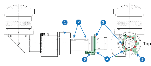 Image 6–2
 - 1
- Lens body
- 2
- Wire clamper
- 3
- M3 cap screws (eight pieces)
- 4
- Interface unit
- 5
- PCBA module

Note: Apply some glue on the head of the screws to prevent loosening when cap screws refastened.
90° rotated
To go from the standard position to a 90° rotated position, turn out the eight M3 screws.
Slide the interface a few mm to the backside of the lens.
Rotate the interface 90° until the red dot on the interface is next to the ‘Up’ mark on the lens body.
Slide the interface back to the front of the lens to re-engage focusing gear and motor gear.
Drive in eight M3 cap screws with some glue.
The lens is ready to be mounted in the projector.
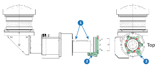
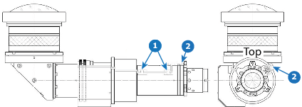 Image 6–6 90° rotated position
- 1
- wire clamper
- 2
- PCBA module
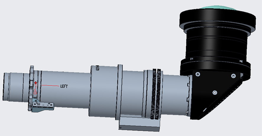
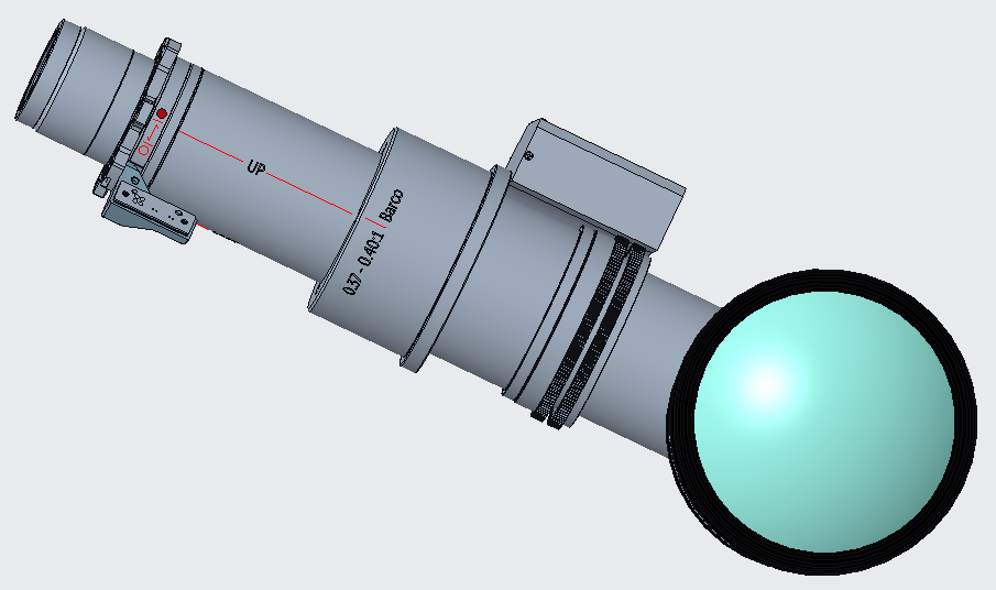 Image 6–7 Up mark on the lens
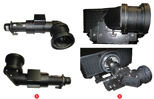
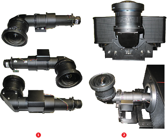 Image 6–8
 - 1
- Wire routing
- 2
- Projection orientation : Up