Components
| Image | Description | Quantity |
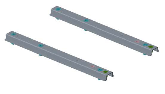 | Beam | 2 |
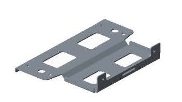 | Base plate | 1 |
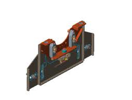 | Lens holder module | 1 |
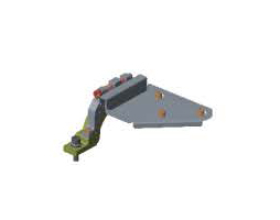 | Lens clamp module | 1 |
 | Safety bar | 1 |
 | Socket head screw M6x12 | 4 |
 | Socket head screw M6x22 | 8 |
 | Spring washer M6 | 8 |
 | Washer M6 | 10 |
 | Socket head screw M4x10 | 5 |

| Image | Description | Quantity |
| Beam | 2 |
| Base plate | 1 |
| Lens holder module | 1 |
| Lens clamp module | 1 |
| Safety bar | 1 |
| Socket head screw M6x12 | 4 |
| Socket head screw M6x22 | 8 |
| Spring washer M6 | 8 |
| Washer M6 | 10 |
| Socket head screw M4x10 | 5 |
Turn the projector up side down. To avoid damage, lay it on a blanket or a foam rubber.
Mount both beams on the bottom of the projector. Use 2 bolts M6x12 and 2 washers M6 for each beam.
Tighten with a torque between 3.5 and 9.8 Nm
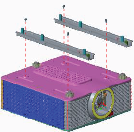
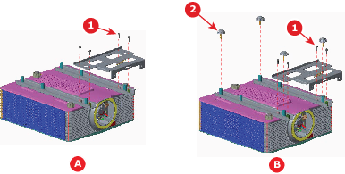
Mount the base plate on the projector beams. Use 4 bolts M6x22 with 4 spring washers M6 and 4 washers M6 (reference 1 in Image 6–10). Insert the spring washer in between the screw head and the washer.
Tighten with a torque between 3.5 and 9.8 Nm
When the projector will be used in table mounting configuration, also turn in the four feet (reference 2 in drawing B).
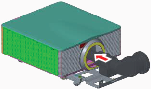
Install the UST lens. Rotate the UST lens clockwise to lock the lens.
The lens holder module is preassembled with screws 2 & 3. Start loosen screws 2 & 3 before starting the next step.
Mount the lens holder module on the base plate with screws with reference 1 and 4 in Image 6–12. Drive them in partially. Use M6x22 screws and insert on each a spring washer M6 and washer M6.

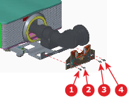
For left projection: mount the lens clamp module on the lens holder module by inserting 2 screws M6x22, 2 spring washers M6 and 2 washers M6. Tighten with a torque between 3.5 and 9.8 Nm
Fixate the adapter plate with 3 screws M4x10 to the lens. To continue, go to step 9.
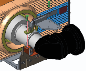
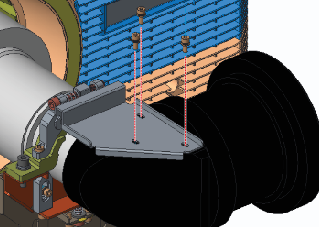
For up projection: adapt the lens clamp module. Remove the lens clamp part from the lens clamp module by removing the 3 screws (Image 6–15. Just mount the lens clamp part on the lens holder module using 2 screws M4x10 (Image 6–16. Tighten with a torque between 3.5 and 9.8 Nm
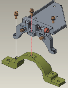
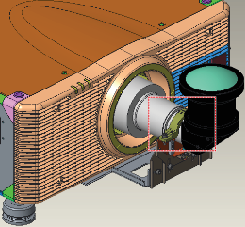
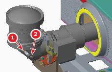
Mount the safety bar with 2 screws M4x10 on the side of the lens (reference 1 & 2 in Image 6–17). This safety bar will be used to mount the safety cable. To continue, go to step 10
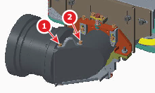
Turn the projector up side down and mount the safety bar with 2 screws M4x10. This safety bar will be used to mount the safety cable.
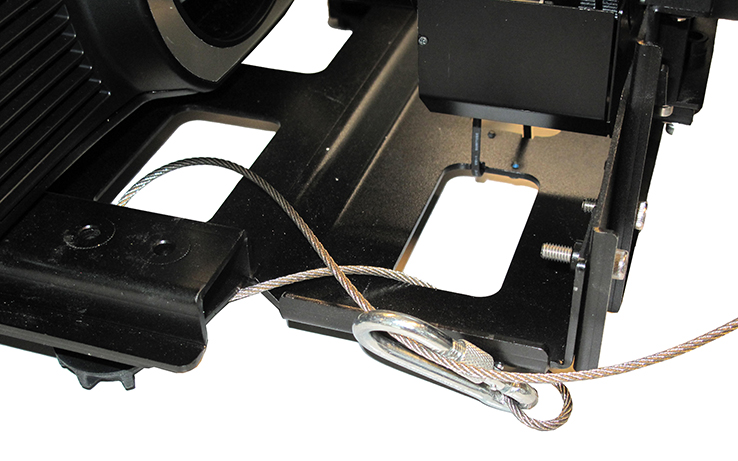
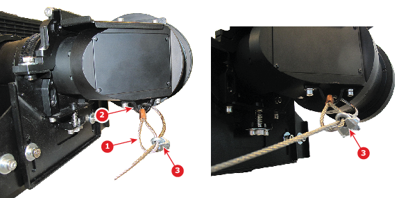
Mount a safety cable through the eye on the safety bar.
Slide the safety cable through the eye (reference 1 on Image 6–19) on the safety bar (reference 2 on Image 6–19) and then through the loop end at the beginning of the cable (reference 1 on Image 6–19).
Install a U-bolt near to the safety eye (reference 3 on Image 6–19). Make sure that both a part of the loop end and the outgoing part of the safety cable are placed in the enclosure.
Close the U-bolt and tighten it.
Place the shackle through the free loop end of the safety cable.
Connect the shackle on the truss or rigging frame. If necessary before connecting the shackle turn the cable a few times around the truss or rigging frame so the play is at a minimum.
If it is not possible to the truss or rigging frame, mount it to the lens support. Turn it a few times around the support so the play is at a minimum and hook the shackle on the cable.