For screen destination, select Screen (reference 10) in the right panel.
For aux destination, select Auxiliary (reference 10) in the right panel.
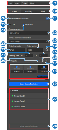
Image 8–54
9
Category selection
10
Output selection
11
New screen destination button
12
Screen destination name input field
13
Output connector resolution drop down
14
Refresh horizontal and vertical pixels button
15
Vertical projection blend area
16
Delete selected output button
17
Create additional output button
18
Screen destination output overview
19
Create new screen destination button
20
Copy output button
21
Horizontal projection blend area
22
Screen destination horizontal pixels input field
23
Screen destination vertical pixels input field
24
Projector screen destination type
25
LED screen destination type
26
Current selection name
27
Screen destination list
28
Delete screen destination button
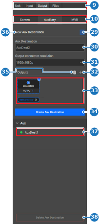
Image 8–55
9
Category selection
10
Output selection
29
New aux destination button
30
Aux destination name input field
31
Output connector resolution drop down
32
Create additional output button
33
Aux destination output overview
34
Create aux destination button
35
Delete selected output button
36
Current selection name
37
Aux destination list
38
Delete aux destination button
Is an existing destination selected?
If yes, click the new destination () button (reference 11, Image 8–54 or reference 29, Image 8–55). Go to next step
If no, go to next step.
Fill out the information about the screen in the New section (reference 12 through 25, Image 8–54 or reference 30 through 35, Image 8–55) of the chosen destination.
Tip: Event Master Toolset will automatically calculate how many output connections are needed to support the entered resolution.
Tip: In case of a projection screen destination (reference 24, Image 8–54), the required blend area (reference 15 and 21, Image 8–54) is calculated based on the entered resolution (reference 22 and 23, Image 8–54).
Tip: Provide clear names that reflect the intended purpose.
Output fields will be created in the Outputs (reference 18, Image 8–54 or reference 33, Image 8–55) overview.
Assign a connector to the generated output field using one of the following methods:
Click on the output field (reference 18, Image 8–54 or reference 33, Image 8–55), then click on the desired connector (reference 4) in the central work area.
Drag the desired output connector (reference 4) from the central work onto the output field (reference 18, Image 8–54 or reference 33, Image 8–55) in the right panel.
Note: Each created field must have a connector assigned.
Note: Clicking on the + icon () to add outputs also increases the total resolution.
Clicking the trash icon () to remove outputs also decreases the total resolution.
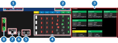
Image 8–56
1
Unit details
2
Screen resource indicator
3
Used/available resource mapping overview
4
Event Master card connector status
5
Genlock connection status
6
LTC connection status (not yet supported)
7
Dante audio connection status (not yet supported)
8
Power connection status
The name of the connector is added below the output field.
Is there more than one output fields in the Outputs (reference 18, Image 8–54) overview? (only for screen destinations)
Click Create Screen Destination (reference 19, Image 8–54) or Create Aux Destination (reference 34, Image 8–55) to configure the outputs.
The selected connectors turn green (reference 4, Image 8–56), the available resources are updated (reference 2, Image 8–56), the destination shows up in the mapped overview (reference 3, Image 8–56) and the name is added to the list (reference 27, Image 8–54 or reference 37, Image 8–55) in the right panel.

 ) button (reference 11, Image 8–54 or reference 29, Image 8–55). Go to next step

 ) in the header.
 ) to add outputs also increases the total resolution.
 ) to remove outputs also decreases the total resolution.