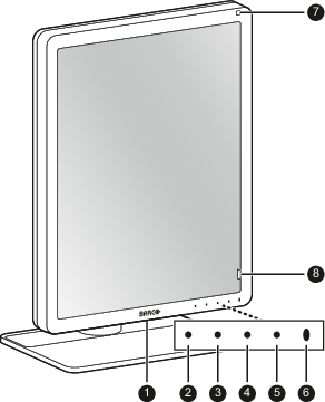
Front
- USB-A 2.0 downstream connector. Charging is possible, only when DPMS mode with USB charging is enabled, or when DPMS is completely disabled (see “DPMS mode”).
- Left / I-Luminate key
- Right key
- Menu key
- Cancel key
Power status LED
- Off: Display not powered, or display operational but power LED function disabled in OSD. See “Power LED”.
- Steady white: Display operational
- Slow blinking amber: Display in standby mode (requires DPMS mode to be enabled in the OSD menu, see “DPMS mode”)
- Fast blinking amber: Display in suspend mode (requires DPMS mode to be enabled in the OSD menu, see “DPMS mode”)
- Steady amber: Display switched off via the standby key, or display in hibernate mode (requires DPMS mode and Hibernate to be enabled in the OSD menu, see “DPMS mode” and “Hibernate”)
- Ambient light sensor
- I-Guard Front sensor