Here, we define system components by adding inputs, backgrounds, outputs and destinations.
C1: Initial Setup
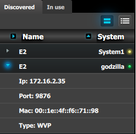
When you connect to an actual unit, instead of working offline, the software should connect automatically. The unit is listed in the System configuration page under the “Discovered” tab with the button on turning green.
Drop the E2 from the device area into the middle diagram area.
If multiple units are connected to the PC, the green LEDs next to the system name will turn green. You can assign a unique name to each unit. In this application we will connect to only one unit and assign the name “Godzilla” to it. For online operations, you can confirm that you are connected to the right unit by clicking the arrow in front of E2 to reveal the unit’s IP address. Verify that this address is the same as the address listed on the unit’s front panel on the top status menu
Image 9–5
Note: If the unit doesn’t connect automatically to the PC, you can type the PC’s IP address in the field under “Manual Connect”.
For this application we will leave the default setting for …
Canvas Mode: PGM and PVW
Preset Conflict Mode: Auto
System Native Rate: 59.94
Genlock: Freerun
C2: Add Background
Click on the top DVI connector of slot 6 to select the input to define as background.
Click on the bottom DVI connector of slot 6 to select the input to define as background.
We need to do this twice because the background comes from a dual-head DVI card. Both DVI Connectors on the card will now be selected.
Click on the “Background” tab in the Adjustment pane to make it active.
Double click on the +Add Single Background button to bind both connectors to a single background input configuration.
Double-click on DVIBackground1 in the Name list to edit the name.
When the area turns blue, click the eraser icon to clear the field.
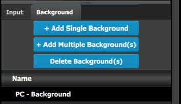
Type a new name, “PC-Background”. Press enter when done.
Image 9–6
Note: In this application only one background is required, but in applications where more than one background is required, repeat the appropriate steps above until done.
C3: Add Input
Click on the first SDI connector of slot 4 to be defined as the camera 1 input.
Click on the “Input” tab in the Adjustment pane to make the Input tab active.
Click on the +Add Single Input button to add that connector as an input for the system.
Double click on SDIInput2 in the Name list to edit the name.
When the area turns blue, click the eraser icon to clear the field.
Type a new name: “CAM1-Stage”. Press enter when done.
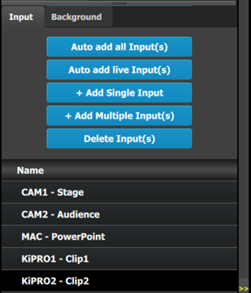
Repeat steps 1 thru 6 for the remaining connectors in Image 9–3. Enter the names as shown in the image below.
Image 9–7
C4: Add Output
Click on the Output tab to make it active.
Click on the first HDMI connector of slot 11 to select it.
Click on the +Add Single Output button to add the output to the system.
Double click on HDMIOutput1 in the Name list to edit the name.
When the area turns blue, click the eraser icon to clear the field and type a new name, “DSM”. Press enter when done.
Repeat steps 2 thru 5 until done to add the rest of the output connectors with the following names:
Site projector (SDI, Slot 13–1)
Main-Left Projector (SDI, Slot 13–3)
Main-Right Projector (SDI, Slot 13–4)
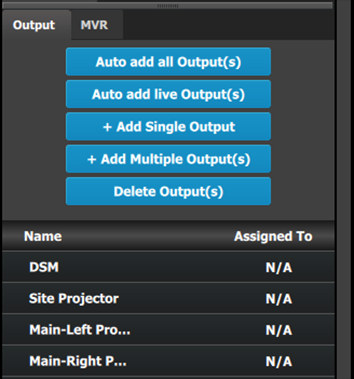
When you are done the menu should look like this:
Image 9–8
Note: The “N/A” at this end refers to the destinations that will be added next.
C5 – Part1: Add Site Screen Destinations
In this section we will create the Site Screen Destination and assign two layers.
Click on the Destination tab to define destinations for the created outputs.
From the diagram area click on the first BNC of slot 13 that is the Site Projector output connector. The BNC will be highlighted.
Click on the +Add Screen Destination blue button to assign the output for the screen destination.
When the destination is created a green rectangle appears next to the E2 diagram.
Double click on the ScreenDest1 area in the Name list to edit the name.
When the area turns blue, click the eraser icon to clear the field and type a new name, “Site Screen”.
Click on the top at the Adjust:Site Screen tab and in the Assign menu under the Output section click on the +Assign Layer to Destination blue button to assign a single link (SL) mix layer to the destination .
In the layout area “1 layer” will appear in the green area of the destination rectangle.
Repeat the Step 7 to add one more layer.
C5 – Part2: Add Main Screen Destinations
In this section we will create the Main Screen Destinations and assign 3 layers.
To create the Main Screen destination, please repeat steps 2 thru 6 of the previous stage (C5–Part1) by first clicking on the “Main-Left Projector” BNC.
Rename the destination to “Main Screen”.
After the destination is created, click on the “Main-Right Projector” BNC and drag it into the “Main Screen” destination box. The Screen size will immediately change to 3840x1080.
Repeat the same steps as above to add a layer to the destination but click the add button 3-times to add 3 layers.
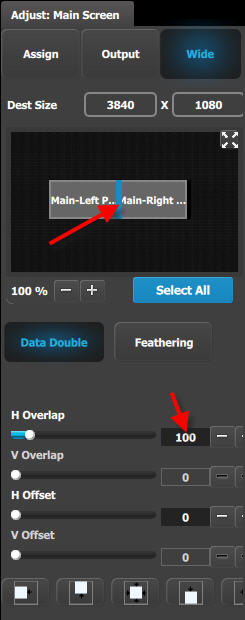
C5 – Part3: adjust the projector overlap in Main Screen destinations
In this section we will adjust the projector overlap area for the Main screen.
Under the Wide menu, the small diagram area shows the destination’s outputs layout. Click on the line between the two rectangles that represent the outputs. The line turns blue.
Click on the Data Double button and enter “100” for the H overlap value. Note: We will leave the feathering disabled (default).
Image 9–9
C6: Add Aux Destinations
From the diagram area click on the DSM output. The connector will be highlighted.
Click on the +Add Aux Destination blue button to assign the DSM output to an Aux destination.
When the Aux destination is created a green rectangle appears next to the E2 diagram.
Double click on the AuxDest1 area in the Name list to edit the name.
When the area turns blue, click the eraser icon to clear the field.
Type a new name, “DSM”. Press enter when done.
Image 9–10
C7: Add MVR Output
Double click on MVROut1 in the Name list to edit the name.
When the area turns blue, click the eraser icon to clear the field and type a new name, “Sources”. Press enter when done.
Double click on MVROut2 in the Name list to edit the name.
When the area turns blue, click the eraser icon to clear the field and type a new name, “Program/Preview”. Press enter when done.
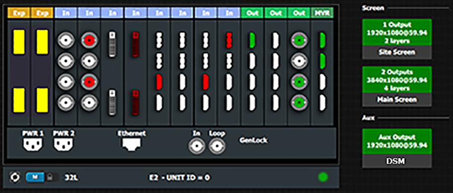
Result
At this stage the layout section of the GUI should look like this: