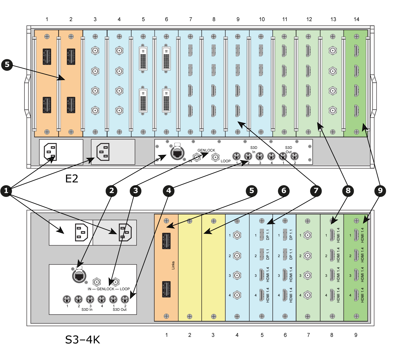
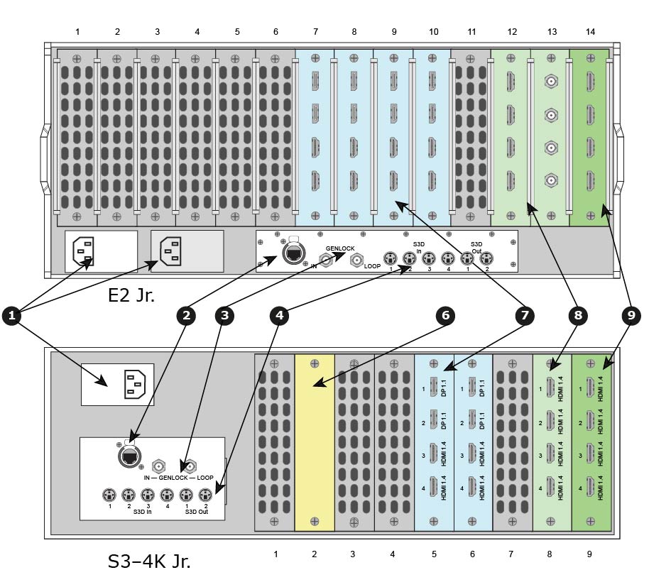
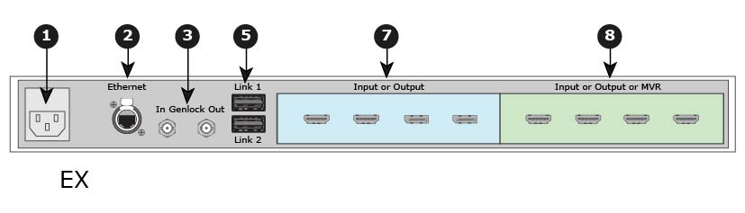
See Image 4–5 for an illustration of the rear panels of the Event Master E2 and S3–4K series processors. See Image 4–6 for an illustration of the rear panels of the Event Master E2 Jr. and S3–4K Jr. series processors. See Image 4–7 for an illustration of the rear panel of the Event Master EX processor.
Image 4–5E2 and S3–4K series rear panels
1
AC connectors
2
RJ-45 connector for 10/100/1000 BaseT Ethernet communications
3
Genlock Input BNC with passive Loop-through
4
S3D In and S3D Out
5
Expansion Link cards
6
VPU cards
7
Input cards (HDMI/DP, SDI, DVI)
8
Outputs cards (DVI, SDI)
9
Multiviewer card (HDMI)
Image 4–6E2 Jr. and S3–4K Jr. series rear panels
1
AC connectors
2
RJ-45 connector for 10/100/1000 BaseT Ethernet communications
3
Genlock Input BNC with passive Loop-through
4
S3D In and S3D Out
–
–
6
VPU card
7
Input cards (HDMI/DP, SDI, DVI)
8
Outputs cards (DVI, SDI)
9
Multiviewer card (HDMI)
Note: The S3–4K Jr. comes with a single power supply; a redundant power supply is optional.
Image 4–7EX rear panel
1
AC connector
2
RJ-45 connector for 10/100/1000 BaseT Ethernet communications
3
Genlock BNC Input and Output
–
–
5
Expansion Links
–
–
7
Input cards (HDMI/DP, SDI, DVI)
8
Outputs cards (DVI, SDI)
8
Multiviewer card (HDMI)
Note: The EX image in Image 4–7 is an example only. The EX expansion box does not ship with cards; cards must be purchased separately.
Table 4–1Comparison of Event Master rear-panel connections
Description
E2
E2 Jr.
S3–4K
S3–4K Jr.
EX
1
AC connectors
2
2
2
1
1
2
RJ-45 connector for 10/100 BaseT Ethernet communications
Event Master E2, E2 Jr., and S3–4K series processors are equipped with two redundant power supplies. During normal operation the load is shared equally by both supplies. If one supply fails, the second carries the whole load. Two AC Connector are provided to connect Event Master series processors to your facility’s AC power source through the supplied power cords. A second power supply is optional on the S3–4K Jr.
Input Power Specification: 100-240 VAC, 47-63 Hz
On each power supply there are 3 LED lights that provide status information as follows:
DC Output Power LED: when Green, the supply is outputting valid DC power.
Status LED: when amber indicates that an error has occurred.
AC Input Power LED: when green it indicates that the supply is connected to a valid AC power.
Therefore, during normal operating conditions, the input AC and Output DC LEDs will turn green.
Note: Note that the power supplies are installed upside down in the E2 model, so the silkscreen markings will also appear upside down. Power supplies in the S3 model are installed in the correct orientation for reading silkscreen markings.
Ethernet port
One RJ-45 connector is provided for 10/100/1000 BaseT Ethernet communications with the Event Master series processor. The port is used for running the Web Interface and for connection to an external device.
The Ethernet connector is compatible with:
Standard RJ-45 Ethernet cables
Neutrik EtherCon® series cables
For pinout details, refer to the section dedicated to the pinout in Appendix A, “Standard connector pinouts”.
Genlock Input BNC (with passive Loop-through)
The Genlock input supports analog NTSC and PAL Blackburst, as well as HD tri-level sync signals, per SMPTE 274M and SMPTE 296M. The passive loop-through connector passes the Genlock signal to another device downstream of the Event Master series processor. The Loop-through output will continue to function even when the device is turned off. When the device is genlocked and the lock source is lost, the output of the unit will automatically switch to “free-run” state without any discernible “glitching” on the output display device. As the loop-thru is passive a 75Ohm termination is necessary for stable operation.
For Genlock connections details, refer to the Specifications Appendix.
Expansion Link cards
When event requirements exceed the capacity of a single unit in terms of input, output, or number of layers, multiple Event Master processors can be linked together through the Expansion Link cards. The cards are connected with Barco-supplied, high-bandwidth, bi-directional Expansion Link cables. These cables are also commercially available.
Depending on the Event Master processor model, two, one, or no slots are reserved at left side of the rear panel for Expansion Link cards.
For more details on capabilities of expansion, refer to the section “Expansion Link Card”.
VPU cards
VPU (Video Processing Unit) cards are at the heart of the Event Master Series of products. All scaling, layer effects and image compositing happens within these cards. Each card supports the scaling requirements for the product line with the award-winning Athena scaling technology at resolutions up to 4K. Due to their reprogrammability any future video processing capabilities will be implemented in these cards. Current capabilities include:
Support for 2K, Dual-Link, and 4K Scaling
Layer compositing over unscaled Backgrounds
Layer effects, including Borders and Shadows
Keying effects
Key frame effects
On an E2 and E2 Jr. units, the VPU cards are not accessible through the rear panel. On S3–4K and S3–4K Jr. units, slots 2 and 3 are reserved for the VPU cards. The EX expansion box has no VPU cards.
For more details on VPU card, refer to the section “VPU Card”.
Input cards
Each input card supports resolutions of up to 4K. The ability of the Event Master processors to support up to 40 inputs (E2 Gen 2) eliminates, in most cases, the need to have upstream routers or scalers.
On an E2 (or an E2 Jr.) processor, slots 3 through 10 are reserved for input cards. On an S3–4K (or an S3–4K Jr.) processor, slots 4 through 6 are reserved for input cards. Both slots of an EX expansion box may hold input cards, but if the EX has both an input and an output card, the input card should go in slot 1.
The following sections describe each type of card in detail:
Event Master series processors support HDMI and SDI output cards. Each output card supports resolutions of up to 4K.
On an E2 (or an E2 Jr.) processor, slots 11 through 13 are reserved for output cards. On an S3–4K (or an S3–4K Jr.) processor, slots 7 and 8 are reserved for output cards. Both slots of an EX expansion box may hold output cards, but if the EX has both an input and an output card, the output card should go in slot 2.
The following sections describe each type of card in detail:
The Multiviewer card is physically identical to the HDMI output card, but when it’s plugged in the last slot it operates as a Multiviewer (MVR), supporting either two (2) HD outputs on the HDMI 1.4 output card, or four (4) HD outputs on the HDMI 2.0 output card. The Multiviewer card is a dedicated, fully integrated monitoring solution that allows multiple displays to be shown together on a single display. Up to 63 MVR windows (sources, backgrounds, or destinations) can be displayed across two (2) outputs: 63 windows for Inputs and 63 windows for Outputs.
From the Multiviewer menu in the EM GUI the user can create customized layouts, texts, backgrounds, borders, or colors for the monitors. The MVR includes several alarms such as Frozen and Loss-of-Signal indicators. For more details on Multiviewer features, refer to the section “Multiviewer (MVR) Menu”.
[4] The EX expansion box internally generates genlock output.
[5] E2 Jr. and S3–4K Jr. do not have expansion Link cards.
[6] The EX has two (2) Expansion Links integrated in the chassis.
[7] VPU cards in the E2 and E2 Jr. are internally mounted.
[8] Each EX expansion box has two general purpose card slots, each of which may support any E2 input or output card.
[9] E2 Jr. and S3–4K Jr. do not have Link cards, but these models can be upgraded with Link cards, which would go into the same slots as the Link cards on the E2 and the S3–4K.
[10] The EX has two (2) Expansion Links integrated in the chassis.