6.12 Configuration Menu > Adjustment > Unit Configuration

General

In the unit configuration adjustments panel, the user can define and adjust unit (device) specific parameters.

How to access the unit configuration adjustments panel
  1. Select the device (unit) that you want to configure. Refer to “Configuration Menu > System diagram area” and see the subsection “How to select device.”

    The device is selected. The device is highlighted in blue in the System diagram area and the name of device is indicated in the Adjustment tab in the Adjustment area.

  2. Click on the Adjustment tab in the Adjustment area.

    The adjustment panel dedicated to the unit is displayed.
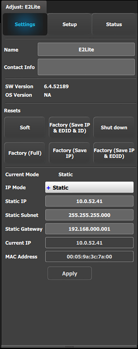
Description

Settings tab:

  • Name: The name of the unit can be edited here.
  • Contact info: User information for contact person responsible for the unit.
  • SW Version: Unit’s Firmware version.
  • OS Version: Unit’s OS version.

    Note: The EM GUI has its Software version shown in the Settings Page.

  • Resets: (If the user selects one of the reset options, a confirmation pop up appears.)

    • Soft: Resets the unit without erasing any stored settings, similar to a Power Off / On.
    • Factory (Save IP & EDID & ID): Full factory reset with the exception of keeping the Ethernet setup (IP), the Input EDID settings, and the Unit ID settings.
    • Shut down: Powers down the unit.
    • Factory (Full): Full factory reset erases all stored settings.
    • Factory (Save IP): Full factory reset with the exception of keeping the Ethernet setup.
    • Factory (Save IP & EDID): Factory reset, but keep IP and Input EDID settings.
  • Ethernet communication setup area.

IP Mode:

  • E2 Lite = 192.168.0.175

If a DHCP IP address is required, the unit can be set to accommodate that too.

The unit can also have a specific IP Address assigned by the user to match a specific network environment.

The IP Address is changed by double-clicking on the STATIC setting and assigning an allowed configuration. For details on Network configurations we refer to industry standard.
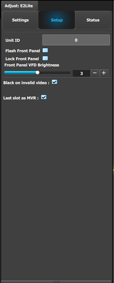
Setup tab:

  • Unit ID: Unique unit identification number.
  • Front Panel: Locks or unlocks the front panel.
  • Front Panel VFD Brightness: Updates the brightness of the front panel VFD.
  • Black on invalid video: If checked, when the input timing on the video does not match what was previously acquired on the input connector the video will be set to black.
  • Last slot as MVR: Allows the operator to use the last slot as an Output or as a Multiviewer (MVR).

    1. Check or uncheck the ‘Last Slot as MVR’ checkbox.
    2. Save the configuration.
    3. Power cycle or soft reset the unit for the change to ‘Last Slot as MVR’ to take effect.

      • To soft reset the unit, go to the Reset section of the Adjust > Settings panel and select ‘Soft.’

    Note: 'Last slot as MVR' is the default setting.

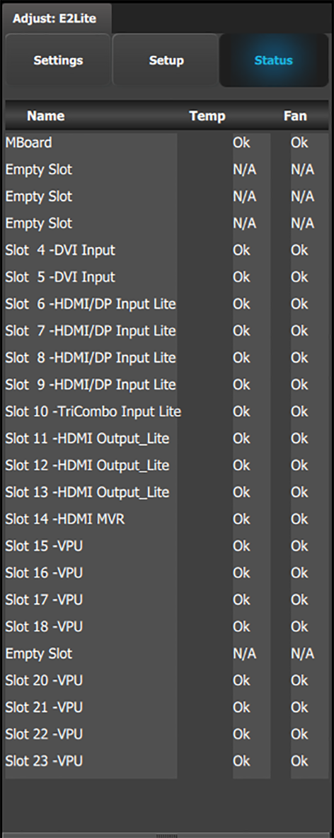
The Status tab shows the name, temperature, and fan status of the motherboard and each card slot.
Last slot as MVR or Output in the simulator

To toggle between using the last slot on the simulator as an Output or as an MVR...

  1. Check the "Last slot as MVR" checkbox in the Setup panel, and press “Save All” to save the settings.
  2. Shut down the simulator.
  3. Edit the simhw.xml file.

    (You may use any XML editor. You may also us Notepad.)

  4. Change the card type of the MVR slot to be either a normal HDMI output card (card type = 22) or an MVR card ((card type = 40).

    Last slot as MVR: <card id="CardID15" type="40" slot="13">CardType_Output_Multiviewer</card>

    Last slot as Output: <card id="CardID15" type="21" slot="12">CardType_Output_4_SDI</card>