General
The system is represented graphically in this part of the System configuration page. It is here that the user can select a system (or create a new one), or select a system element ( inputs, outputs, destinations …)
The system is represented graphically in this part of the System configuration page. It is here that the user can select a system (or create a new one), or select a system element ( inputs, outputs, destinations …)
The diagram area graphically represents the devices and destinations that compose the system.
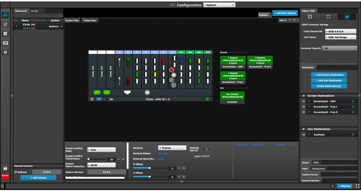
In this area, the rear panel of the selected system is represented graphically with the cards, and the connectors are color coded to indicate their status.
The color code is:
Purple = Connector capacity set to SPLIT; connector 3 mirrors connector 1 (and connector 4 mirrors connector 2), and connector is unavailable to add and configure.
Split-mode may be used with the DisplayPort connectors on the quad channel DisplayPort output card and the SDI connectors on the tri-combo output card.
On the right hand side of the devices is a list of the created destinations (Screen and Auxiliary).
The tabs on the top allow access to the different systems connected to the EM GUI. The last tab allows the users to create a new system.
A set of zoom buttons allows the user to reduce or enlarge the view size. This functionality is very useful when the system is composed of more than one device.
Click on the Add New System tab on the top.
A new empty tab is created.
Change the system name to avoid confusion when you control more than one system on the same Event Master Toolset Software.
Double click on the tab, the tab background changes to a dark blue color indicating that modifications to the name can be made.
Click on the “X” button on the system tab.
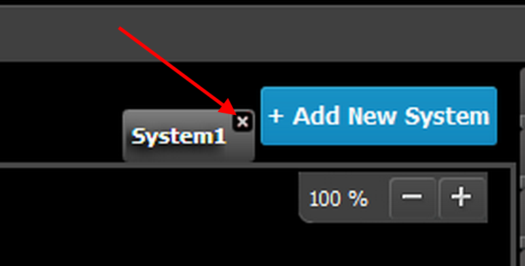
A confirmation window appears.
Click on OK.
The tab is removed.
Click on the area situated below the Event Master series processor graphic representation.
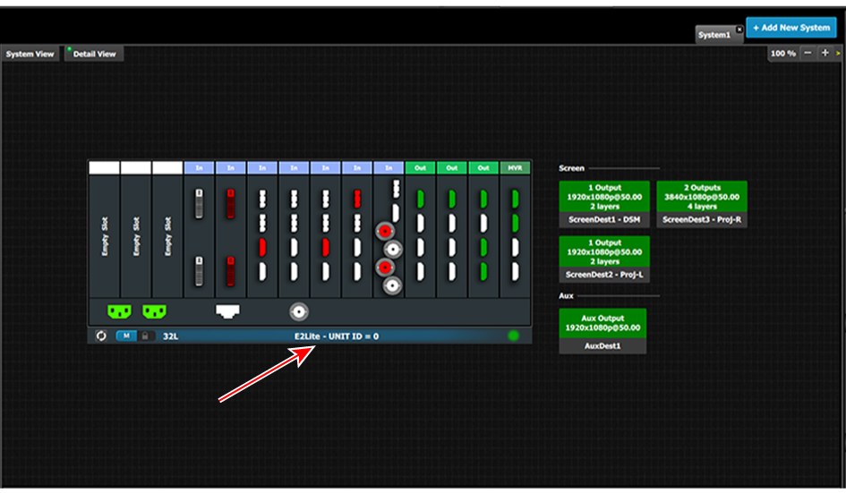
The device is selected. The device is highlighted in blue.
Click on a destination (e.g. Aux).
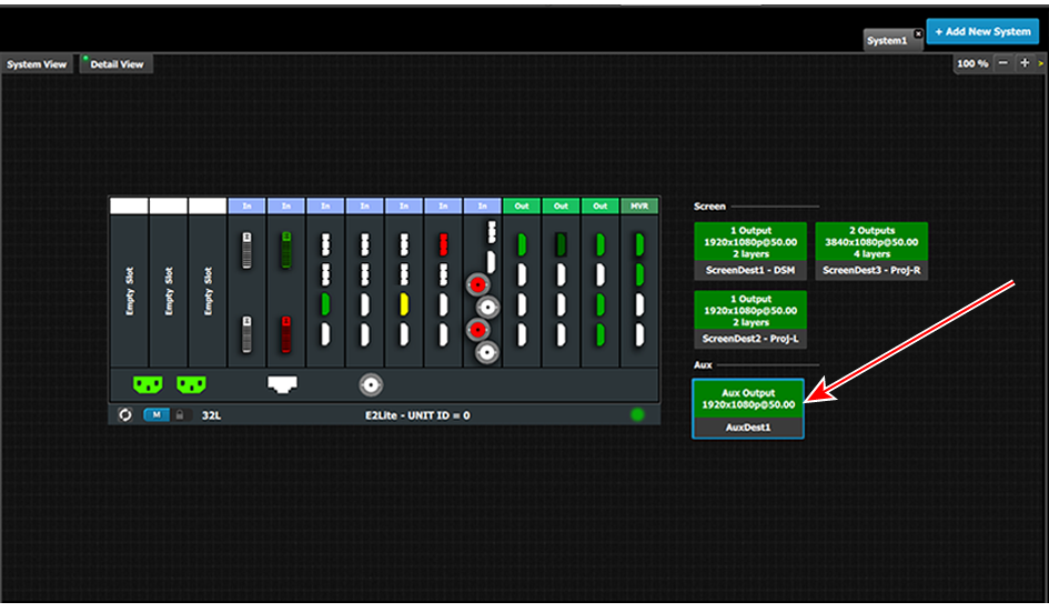
The destination is selected. The destination is highlighted in blue.