Add, delete, and adjust Destinations with the Destination and Destination Adjust panels.
How to add Destination(s)
To assign an output configuration to a destination...
Select the output configuration (Output tab).
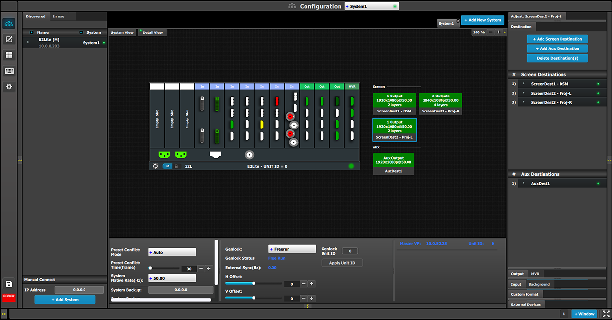
Click on the Add Screen Destinationor the Add Aux Destination button (Destination tab).
These buttons are highlighted in blue.
Image 6–23Add destination buttons
If the Add destination button is pressed without selecting an output configuration, the software will automatically assign the first unassigned output configuration (from left most output card) to a destination. The output configuration format is copied to the destination output format.
New Screen or Aux destinations can be added as long as there are unassigned output configurations to destinations.
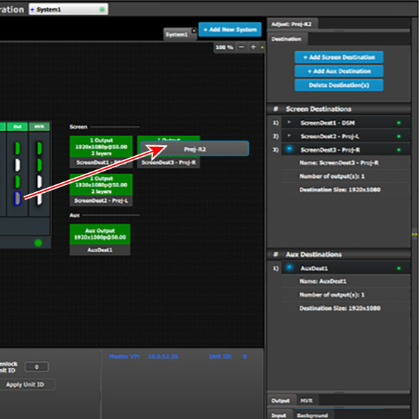
Alternatively, you assign outputs to destinations by dragging them into the Destination block. In the example below, the output 1 was assigned to ScreenDest1 and the destination format was set to 1920x1080 reflecting the format of output1.
When output 2 is dragged into the same destination, then the format changes to 3840x1080 reflecting a 2x1 setup. When outputs are dragged into a destination in this manner, the software assumes it is a horizontal setup with 0 pixel overlap. The overlap can be modified in the Wide menu. If a vertical or grid setup is desired, then the output configuration needs to be setup as such in the output configuration menus.
Image 6–24Add Output to Destination
How to delete Destination
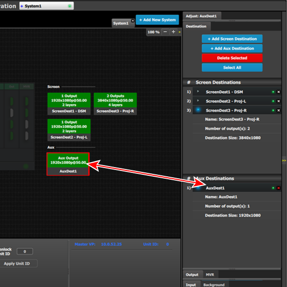
Click on the Delete Destination(s) button The Delete Destination(s) button is replaced by the Delete Selected button (highlighted in red) and the unit diagram is greyed out, except the area dedicated to destinations (Screen and Aux).
Click on destination in the graphical area.
or
Click on the “x” on the right hand side in the destination configuration list.
Destination(s) is immediately outlined in red.
Image 6–25Delete selected Destination(s)
The deletion is completed by clicking the Delete Selected button.
Note: Any output can be deleted from a destination at any time. For example, if the output that is automatically assigned to a destination is not the desired one, then it can be deleted.
Note: All destinations can be deleted the same time by clicking the “Select All” button.
How to access to the Destination configuration adjustments
Adjustments to Destinations are performed in the “Adjust” panel:
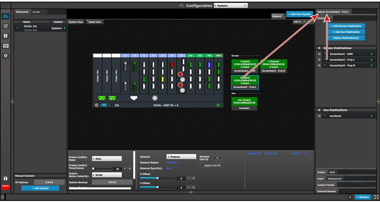
Select the destination from the configuration list.
or
Click on the graphic representation the destination in the Diagram area.
A Destination is selected.
Click on the Adjust tab that is on the top of the Adjustment area.
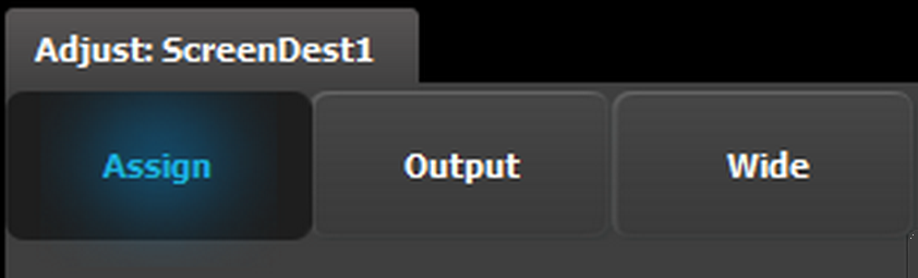
Image 6–26Destination Adjust tab
The Destination adjustment panel is displayed.
Destination adjustment panel description
The Destination adjustment panel is divided in three sections:
Assign
Output
Wide
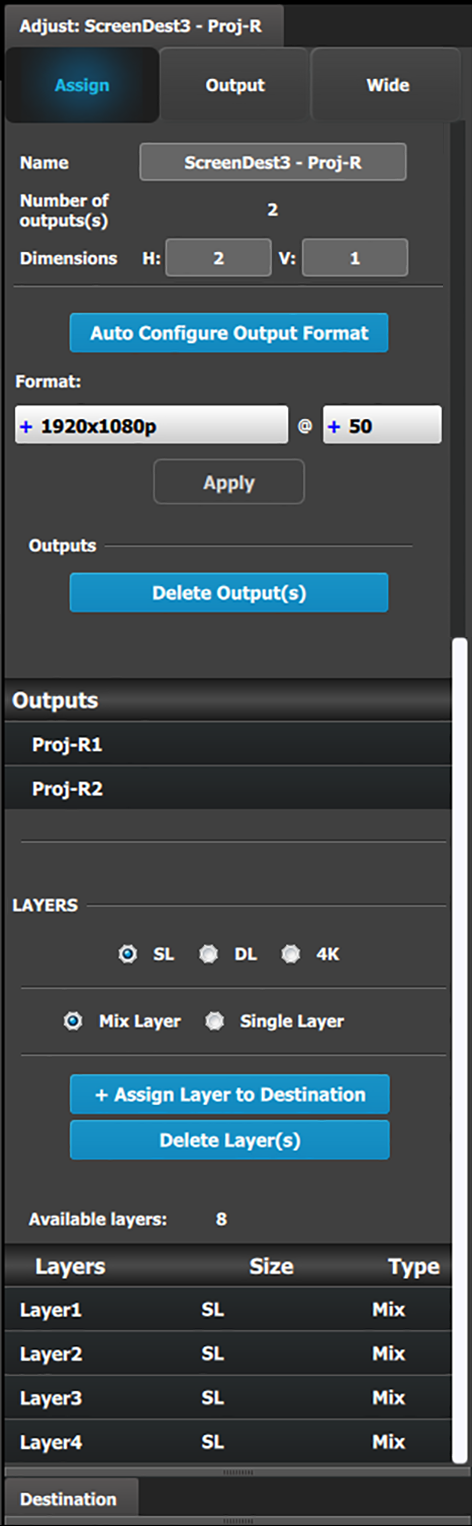
Assign Menu
Name: Adjusts the name of the Destination.
Destination type: Reports the type of destination Screen or Aux. Can convert from Screen to Aux if it meets requirements.
Number of output(s): Reports the number of output configurations in the destination.
Dimension: Adjust the output configuration layout .
Auto configure Output format: Reads the EDID information of the connected device to acquire its format. If more than one device is connected to the destination, it reads the format of the first output. This feature is not available for SDI outputs.
Output(s) format: Adjusts the output format of the destination. This is applied to all outputs that are added into this destination.
If you cannot find the output format in the list, it is possible that the connector capacity for the connector is too small. Remove the outputs from the Destination; update the connector capacity; and check again. (Refer to “Configuration Menu > Adjustment > Output Configuration”, and see the subsections "How to delete Output" and "Output adjustment panel > Connector Menu.")
Output rotation icons: Adjust the counterclockwise rotation of the Output of a Screen or an AUX Destination. The rotation can be 0°, 90°, 180°, or 270°. The default rotation is 0°.
When a Destination is rotated, the Output AOI setting is reset to full, and new min and max values are applied. For example, when an AOI with a rotation of 0° is 1920x1080, then that same AOI with 90° rotation is 1080x1920.
When a Destination is rotated, the Destination cannot be in minimum delay.
Rotation adds an extra frame of delay;
Minimum delay capable Screen Destinations that are rotated have 1 frame of delay.
Non-minimum delay capable Screen Destinations that are rotated have 2 frames of delay.
AUX Destinations have 1 frame of delay.
Rotated AUX Destinations have 2 frames of delay.
When a Destination is rotated, the canvas is accordingly resized.
When a Destination is rotated, the Screen Destination as a source to a Layer is not rotated.
Note: The Output rotation icons are available only for Output from the Quad DisplayPort 1.2 Output card and from the Tri-Combo Output card.
Outputs: Provides a list of the output configurations assigned to the Destination.
For Aux destinations, only 1 Output configuration is shown or is allowed to be defined. From this menu outputs can be deleted or added as in the output configuration menu.
Layer (only applicable when Destination is a Screen). You can assign a size to the Layer: SL (2K Single Link), DL (Dual Link), or 4K. You can also make the Layer either a Mixing Layer or a Single Layer.
The list shows the Layers assigned to this Destination.
A word about layers
Adding to the general description above about layers, mores specifically a EMP´s Screen Destination has 1 fixed Mixing layer, its BG. Then there are a number of mixing layers available in the system.
The E2 Lite has 2 Banks of 8 Mixing Layers for a total of 16 Mixing Layers or 32 Single Layers (32L). These 16 Mixing Layers can be assigned to Destinations, using up to 4 Outputs (1 Bank). If a Destination uses Outputs from both Banks, the Mixing Layer count is reduced to 8.
The layer system has been optimized in E2 Lite to allow the maximum available layer count at all times and can therefore be a bit confusing.
Based on the Layer mode (“2K HD” or “Dual Link”: set in the System Modifier Panel), the number of “Assign Layer to Destination” varies. The maximum number of Single Layers available to an E2 Lite processor are 32 for 2K HD, and 16 for Dual Link.
Note: Layers need to be assigned to destinations before sources can be added to the destination.
Output menu
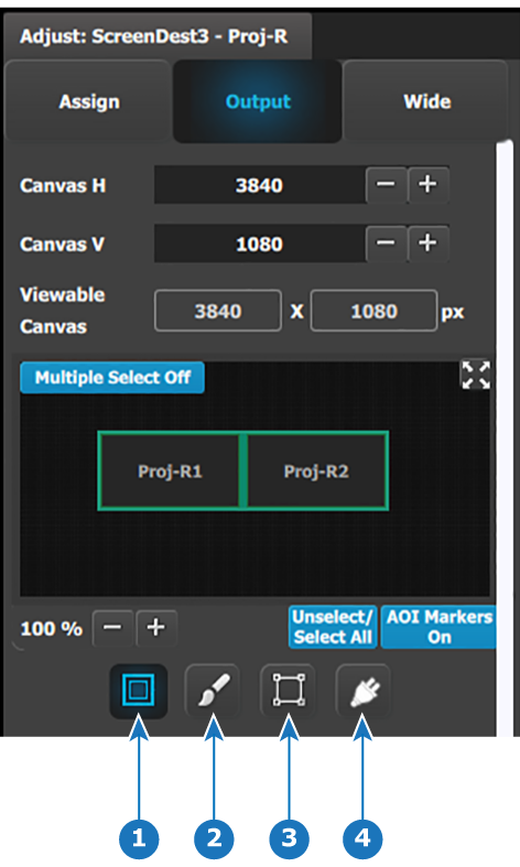
The Output Menu contains four sub-menus: Main, Color, Timing and Connector properties. Adjustments to the Main, Timing, and Connector properties are identical with the adjustments to the Main, Timing, and Connector properties in the output configuration menu. In this destination configuration menu, however, adjustments can be performed on all or on selected outputs that make up the destination. Individual outputs can be selected by clicking on the corresponding screen. When a screen is selected its outline turns blue. All outputs can also be selected by clicking on the Select All button.
Image 6–27Configuration Menu: Destination Adjust—Output (Top of panel)
1
Main
2
Color
3
Timing
4
Connector properties
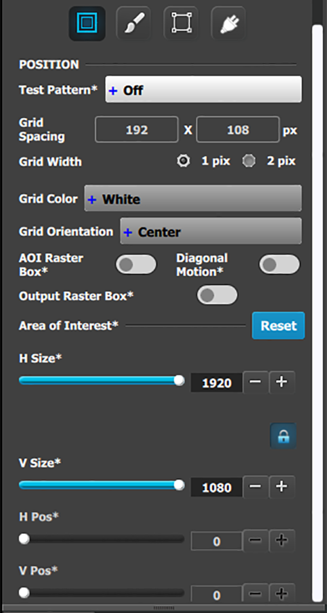
Output menu – Main submenu
Operate similarly to the Output adjustment panel > Main menu.
Test pattern: Turns the Test Patterns ON and select the desired type. The default setting is OFF. Test pattern types:
– Horizontal Ramp
– Horizontal steps
– Vertical Ramp
– Vertical steps
– 100% Color Bars
– White
– 16x16 Grid
– Black
– 32x32 Grid
– SMPTE Bars
– Burst
– H Alignment
- –75% Color Bars
– V Alignment
– 50% Gray
– H V Alignment
– Circle Alignment
Raster box: Turns ON or OFF on a raster around the default active area. This raster box is a white, single-pixel-wide broken line.
Diagonal Motion: Turns the Diagonal Motion ON or OFF for select patterns:
The motion is a bottom-right to top-left diagonal for 16x16, 32x32 grid.
The motion is right to left for 100% Color Bars.
There is no motion in Horizontal and vertical Ramps and other patterns.
Area of Interest (AOI): A raster box that can be positioned and sized within the outputs active area, it effectively makes the AOI the new active area.
This raster box is a green, single-pixel-wide broken line that helps you adjust the AOI within the output’s active area The handles for the AOI menu are:
H Size and V size: Adjusts the horizontal and vertical positions respectively.
H Pos and V pos: Adjusts the horizontal and vertical positions respectively.
Note a lock button allows user to lock the aspect ratio of the size.
Reset button: resets the AOI to default which is the full output area.
Operate similar as the Output adjustment panel > Main page. See above.
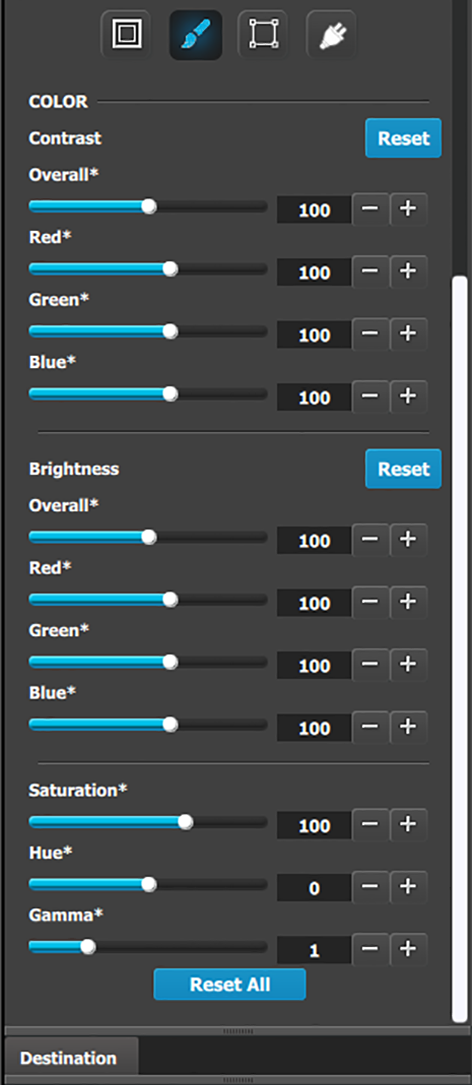
Output menu – Color submenu
The Output Effects Submenu adjusts color variable of the output image, such as contrast and brightness, saturation, hue and gamma corrections.
The RGB Contrast and Brightness settings are adjustable.
The Overall adjustment has a range of 50 to 150.
The individual Red/Green/Blue adjustments have a range of 25 to 150.
The default setting for all of these properties is 100.
Saturation is adjustable within a range of 0 to 150. The default setting is 100.
Hue is adjustable within a range of –90 to +90 degrees. The default setting is 0 degrees.
Gamma is adjustable within a range of 0.31 to 3.29. The default setting is 1.0.
Reset All changes all values to their default settings.
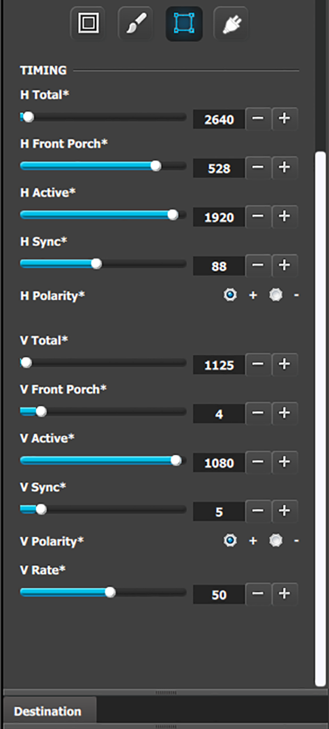
Output menu – Timing submenu
Operate similarly to the Output adjustment panel > Timing menu.
Format: Selects the video format of the output configuration from the drop menu. This is the same adjustment as in the previous menu.
H Total: Adjusts (in pixels) the total pixel count per line for the selected output.
H Front Porch: Adjusts (in pixels) the offset between the end of the output active area and the beginning of H sync.
H Active: Adjusts (in pixels) the horizontal size of the output active area.
H Sync: Adjusts (in pixels) the H sync width.
H Polarity: Adjusts the polarity (active High or Low) of the horizontal sync pulse (N/A in SDI).
V Total: Adjusts (in lines) the total line count per frame.
V Front Porch: Adjusts (in lines) the offset between the end of the output active area and the beginning of V sync.
V Active: Adjusts (in lines) the vertical size of the output active area.
V Sync: Adjusts (in lines) the V sync width.
V Polarity: Adjusts the polarity (active High or Low) of the vertical sync pulse (N/A in SDI).
V Rate: Adjusts the frame rate in seconds polarity (active High or Low) of the vertical sync pulse (N/A in SDI).
Note: Changing these values can make the video signal undetectable for other devices. Always use a VESA timing calculator for best results.
Output menu – Connector submenu
Operate similarly to the Output adjustment panel > Connector menus.
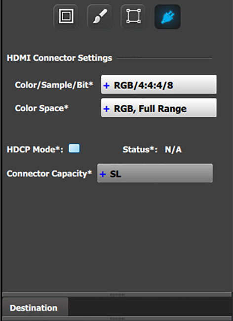
HDMI Connector submenu
HDMI Connector submenu
Color/Sample/Bit: Choices are:
– RGB/4:4:4/8
– YCbCr/4:4:4/8
– RGB/4:4:4/10
– YCbCr/4:4:4/10
– RGB/4:4:4/12
– YCbCr/4:4:4/12
– YCbCr/4:2:2/12
Color Range: Choices are:
RGB, Reduced Range (Values 16–235, television and movies)
RGB, Full Range (Values 0–255, computer monitors)
SMPTE, Full Range
SMPTE, Reduced Range
HDCP Mode: HDCP Mode enables the HDCP setting for the selected output. The default for HDMI outputs is Off. To turn On the HDCP Mode, click on the empty checkbox. When the checkbox displays a check mark, HDCP Mode is On. HDCP Mode is not applicable to SDI outputs.
Connector Capacity: If the connector is not assigned to a destination as above the capacity can be changed. Once included in a Destination configuration this needs to be managed thru the Adjust pane of the Destination.
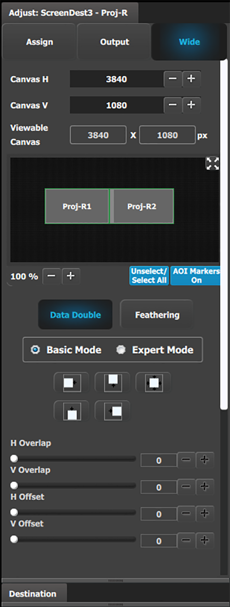
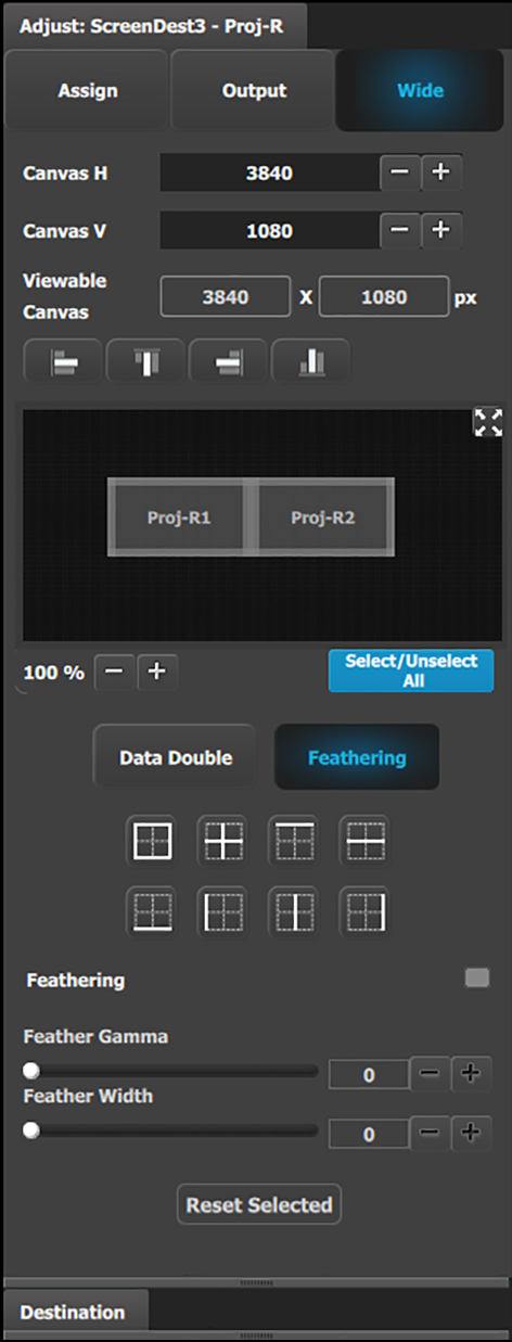
Wide (screen) menu
In this menu, the user can adjust the data-doubling and feathering parameters necessary to setup a wide blended screen. These actions can be performed simultaneously on all screens by clicking the “Select All” button. The data-doubling parameters can be adjusted in either Basic Mode or Expert Mode.
Data-doubling submenu—Basic Mode
Canvas H: This is the horizontal size of the canvas, measured in pixels. The edit box allows the user to adjust this size.
Canvas V: This is the vertical size of the canvas, measured in pixels. The edit box allows the user to adjust this size.
Viewable Canvas: Viewable Canvas displays the horizontal and vertical size of the viewable canvas in pixels. This is the area that the Outputs cover in the canvas.
Data Doubling H or V Overlap width: The adjustment can be made by moving the slider, entering the value manually in the box, or clicking on the plus and minus.
Note: The Overlap sliders are disabled, until at least one overlapping area is selected. Gray overlaps are unselected; blue overlaps are selected. Individual overlaps can be selected by clicking on the desired overlap in the output image. All overlaps can be selected by clicking on the Select All button.
Once an overlap is created, H and V offset can be adjusted for Left, Right, or Center justification.
The icons above the sliders are shortcuts for the offset.
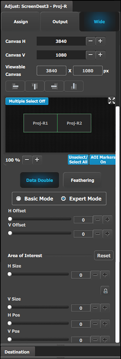
Data-doubling submenu—Expert Mode
The top part of the panel is the same in Expert Mode as it is in Basic Mode. Expert Mode, however, offers greater control over horizontal and vertical Offset and Size. Expert Mode also allows the user to add Outputs without increasing the canvas size and to place those Outputs anywhere within the canvas.
Data Doubling H or V Overlap width: The adjustment can be made by moving the slider, entering the value manually in the box, or clicking on the plus and minus.
Note: The Overlap sliders are disabled, until at least one overlapping area is selected. Gray overlaps are unselected; blue overlaps are selected. Individual overlaps can be selected by clicking on the desired overlap in the output image. All overlaps can be selected by clicking on the Select All button.
Once an overlap is created, H and V offset can be adjusted for Left, Right, or Center justification over the Background.
The Area of Interest (including H Size and V Size) is duplicated here from the Output tab, so that the user can adjust the AOI and the X/Y Offset together.
The icons above the sliders are shortcuts for the offset.
Feathering submenu
Canvas shows the actual pixel ratio for the full blend.
Select the region where feathering will be performed. All edges can be separately selected and have a different value of Feather and Gamma. The adjustment can be made my moving the slider, entering the value manually in the box or click on the plus and minus.
Note: The Feathering and Gamma sliders are disabled, until at least one edge that can be feathered is selected. Gray edges are unselected; blue edges are selected.
Activate or deactivate the feather for the selected edge by checking the Feathering checkbox.
Adjust the Feathering Gamma (shape of the curve) and the width of the feathering region.
The icons above are shortcuts for edge selection.
The Arrow icon allows the small windows representation of the blend to be copied to the workspace for ease of edge selection.