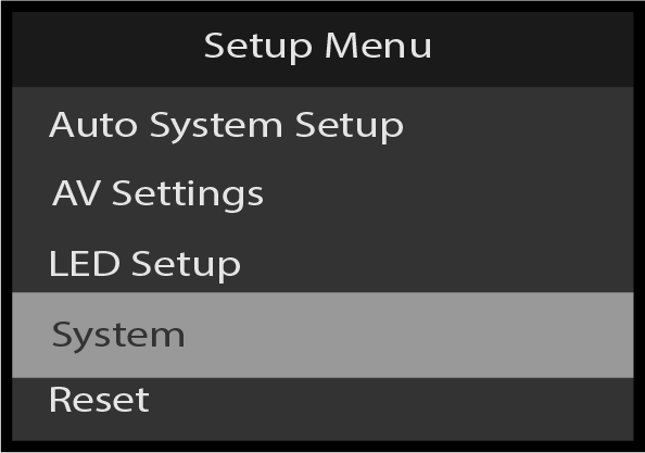
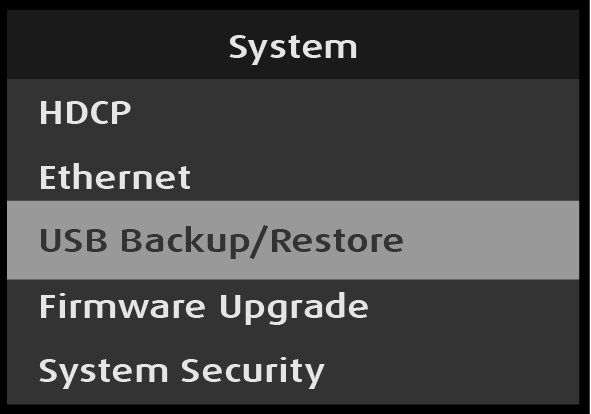
Use the Setup Menu: System menu to set up and adjust system attributes. To enter the System menu from the Setup Menu, scroll to and select System.
Image 5–213Setup Menu: System menu selection
Use the System menu to adjust system parameters.
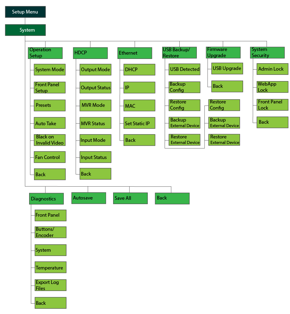
The Setup Menu: System menu has the following submenus:
Operation Setup
HDCP
Ethernet
USB Backup/Restore
Firmware Upgrade
System Security
Diagnostics
Autosave
Save All
Back
Setup Menu: System menu tree
Refer to Image 5–214 for an illustration of the Setup Menu: System menu tree.
Image 5–214Setup Menu: System menu tree
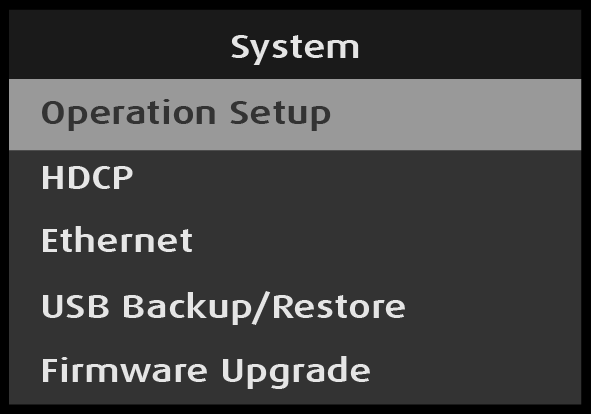
System: Operation Setup
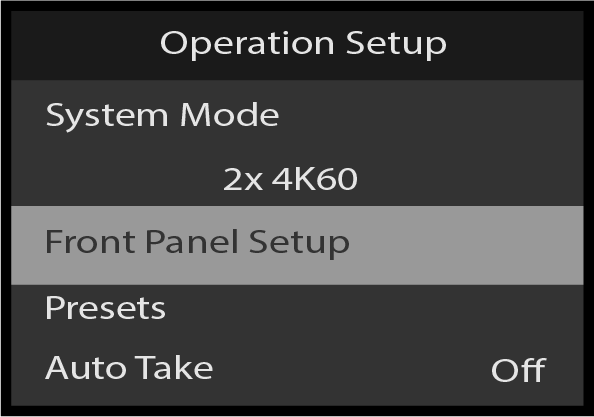
Select Operation Setup on the System menu.
Image 5–215System: Operation Setup selection
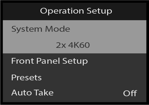
Operation Setup: System Mode
Use Operation Setup: Mode to view the output mode.
Select System Mode on the Operation Setup menu.
Image 5–216Operation Setup: Mode selection
Operation Setup: System Mode is used to switch between: 2x 4K60 and 4x 4K30 output.
2x 4K60 Mode configures the system to process all inputs and two Program outputs up to a maximum format of 3840x2400 @60Hz.
4x 4K30 Mode configures the system to process all inputs and four Program outputs up to a maximum format of 3840x2400 @30Hz.
Operation Setup: Front Panel Setup
Use Operation Setup: Front Panel Setup to adjust the operation of the front-panel buttons.
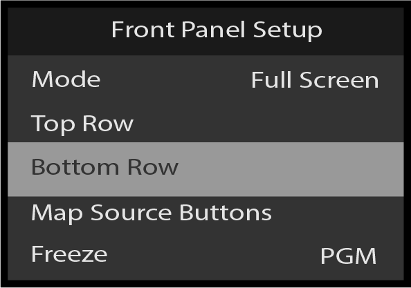
Select Front Panel Setup on the Operation Setup menu.
Image 5–217Front Panel Setup selection
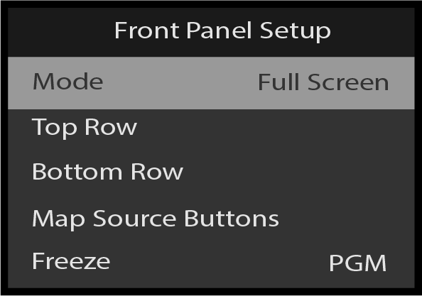
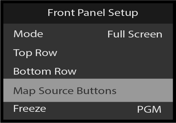
Front Panel Setup: Mode
Use Front Panel Setup: Mode to view the front-panel mode.
Select Mode on the Front Panel Setup menu.
Image 5–218Front Panel Setup: Mode selection
Front Panel Setup – Top Row
Use the Front Panel Setup: Mode menu to change the operational mode of the front panel buttons from Full Screen to Presets/Cues. See more about these front panel operation modes in “Front panel”.
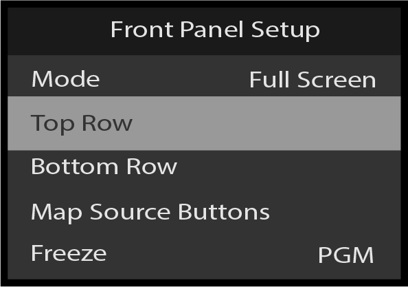
Select Top Row on the Front Panel Setup menu.
Image 5–219Front Panel Setup: Top Row selection
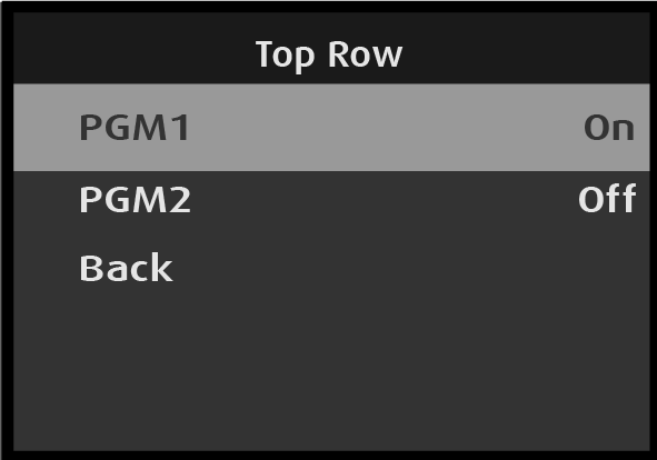
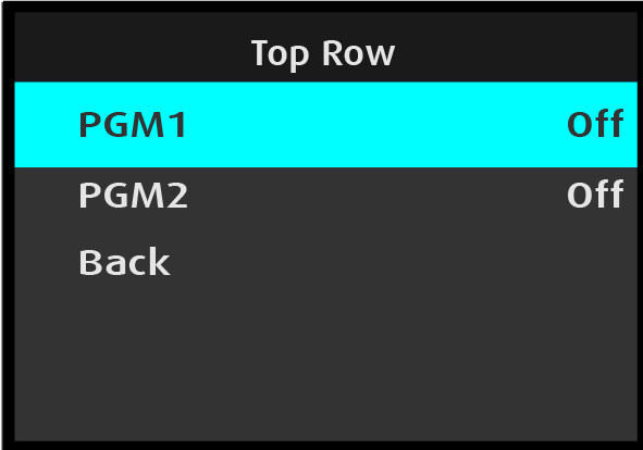
Selecting Top Row opens the Top Row menu.
Image 5–220Top Row menu
Select the desired output.
Once the desired output is selected, the highlight bar turns from gray to cyan. Turning the adjust knob toggles between Off and On.
Image 5–221Top Row: Output adjustment
Use the Adjust knob to turn the output control On or Off.
Repeat steps #2 and #3 for other desired outputs.
Note: For Top Row, Bottom Row, and Source Buttons, in 2x 4K60 mode the options are PGM1 and PGM2; in 4x 4K30 mode the options are PGM1A, PGM1B, PGM2A, and PGM2B.
Front Panel Setup – Bottom Row
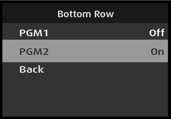
Select Bottom Row on the Front Panel Setup menu.
Image 5–222Front Panel Setup: Bottom Rom
Selecting Bottom Row opens the Bottom Row menu.
Image 5–223Bottom Row menu
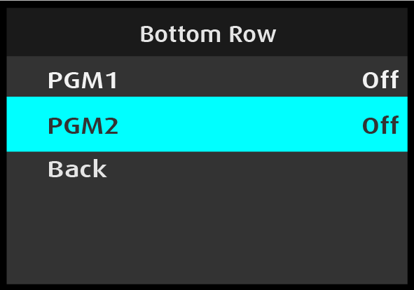
Select the desired output.
Once the desired output is selected, the highlight bar turns from gray to cyan. Turning the adjust knob toggles between Off and On.
Image 5–224Bottom Row: Output adjustment
Use the Adjust knob to turn the output control On or Off.
Repeat steps #2 and #3 for other desired outputs.
Note: For Top Row, Bottom Row, and Source Buttons, in 2x 4K60 mode the options are PGM1 and PGM2; in 4x 4K30 mode the options are PGM1A, PGM1B, PGM2A, and PGM2B.
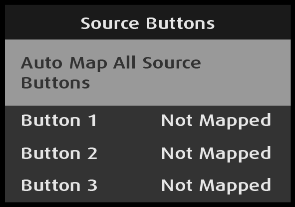
Front Panel Setup: Map Source Buttons
Select Source Buttons on the Front Panel Setup menu.
Select Auto Map All Source Buttons on the Source Buttons menu.
Image 5–226Source Buttons: Auto Map All Source Buttons selection
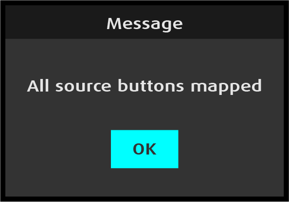
Once Auto Map All Source Buttons is selected, the system unmaps all source buttons, and then the system auto maps source buttons 1 through 8. Once these buttons are mapped, the system displays a message.
Image 5–227“All source buttons mapped” message
Press the Adjust knob to select OK.
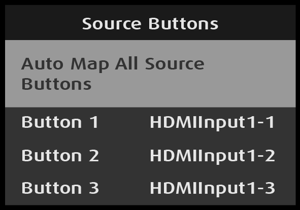
The system returns to the Source Buttons menu and displays the inputs that are mapped to the buttons.
Image 5–228Source Buttons: Auto Map All Source Buttons mapped
Scroll to and select Back to return to the Front Panel Setup menu.
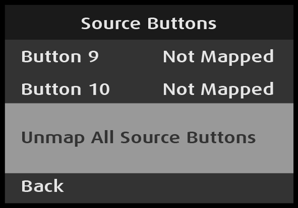
Source Buttons: Unmap All Source Buttons
Select Unmap All Source Buttons on the Source Buttons menu.
Image 5–229Source Buttons: Unmap All Source Buttons selection
Once Unmap All Source Buttons is selected, the system unmaps all source buttons. The system gives no warning message.
Scroll to and select Back to return to the Front Panel Setup menu.
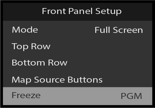
Front Panel Setup: Freeze
Scroll to Freeze in the Front Panel Setup menu.
Image 5–230Front Panel Setup: Freeze
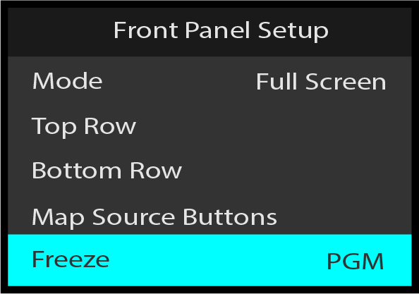
Select Freeze, and choose the desired setting for the Freeze button.
Image 5–231Front Panel Setup: select PGM
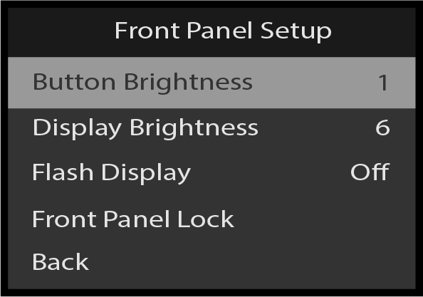
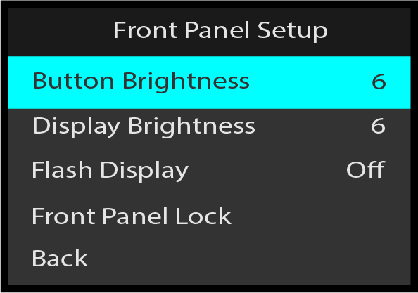
Front Panel Setup: Button Brightness
Use Front Panel Setup: Button Brightness to adjust the brightness of the front-panel buttons.
Select Button Brightness on the Front Panel Setup menu.
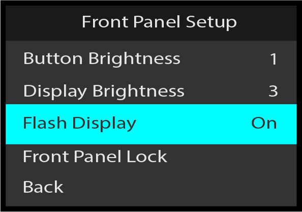
Scroll between Off (default) and On, and select the desired setting.
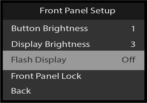
When Flash Display is set to On, the display flashes from dark, to dim, to bright.
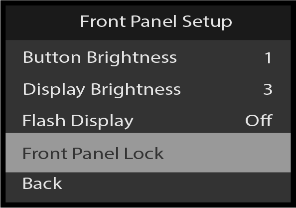
Front Panel Setup: Front Panel Lock
Use Front Panel Lock to lock the front-panel buttons.
Scroll to and select Front Panel Lock on the Front Panel Setup menu.
Image 5–238Front Panel Setup: Front Panel Lock selection
Once Front Panel Lock is selected, the system displays the following message:
Image 5–239“Front Panel Locked” message
Press and hold the ESC button to unlock the front-panel buttons.
Once the front-panel buttons are unlocked, the system displays the Status menu.
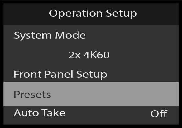
Operation Setup: Presets
To enter the Presets menu from the Operation Setup menu, scroll to and select Presets.
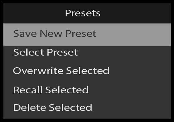
Image 5–240Operation Setup: Presets
To save the current settings as a new preset, scroll to and select Save New Preset. This will immediately save the preset with standard preset name. A message confirming the save will momentarily pop-up.
Image 5–241Presets: Save New Preset
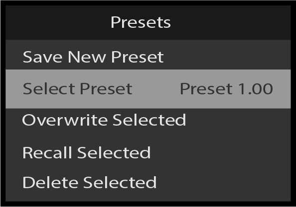
To select and activate one of the saved Presets, scroll to and select Select Preset.
Image 5–242Presets: Select Preset
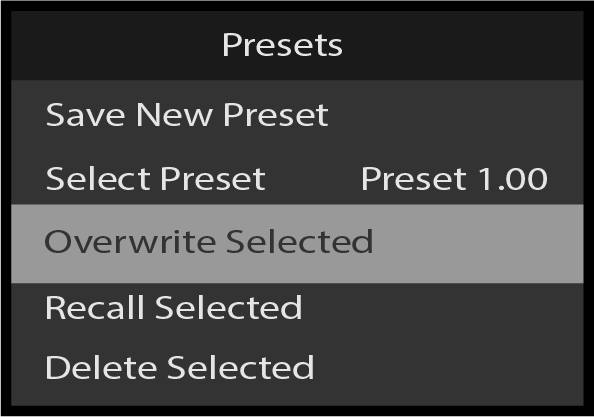
To overwrite the currently selected Preset, scroll to and select Overwrite Selected. A message confirming the overwrite will momentarily pop-up.
Image 5–243Presets: Overwrite Selected
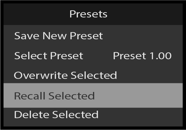
To recall the selected Preset, scroll to and select Recall Selected.
Image 5–244Presets: Recall Selected
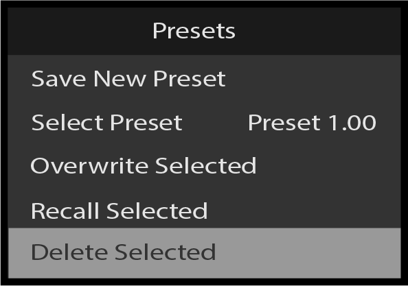
To delete the currently selected Preset, scroll to and select Delete Selected. A pop-up will ask for confirmation. Deletion will be confirmed by a momentary pop-up message.
Image 5–245Presets: Delete Selected
To return to the Operation Setup menu, scroll to and select Back.
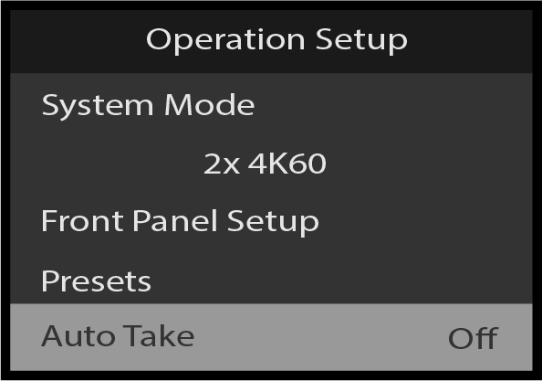
Operation Setup: Auto Take
In Full Screen mode, the top row and bottom row buttons each control a separate screen or group of screens. When “Auto Take” is off, selecting a source places that source in PVW for the assigned output. When “Auto Take” is on, selecting a source transitions that source immediately to PGM for the assigned output. Full Screen mode is the default operational mode for the front panel.
Scroll to and select Auto Take on the Operation Setup menu.
Image 5–246Operation Setup: Auto Take selection
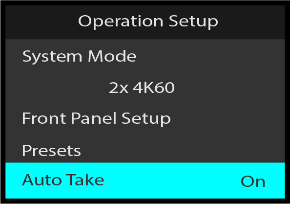
Once Auto Take is selected, the highlight bar turns from gray to cyan.
Image 5–247Operation Setup: Auto Take adjustment
Turn the Adjust knob to toggle Auto Take On and Off.
Press the Adjust knob to select the desired Auto Take value.
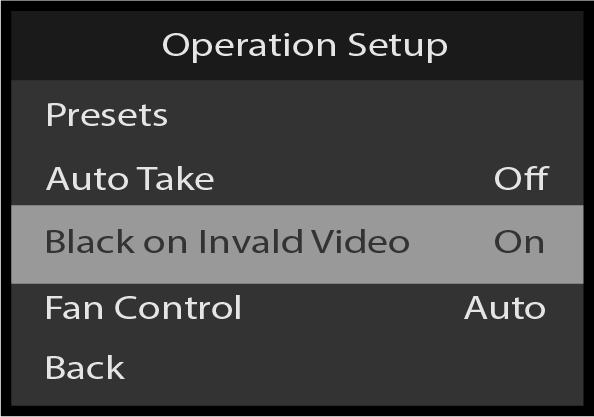
Operation Setup: Black on Invalid Video
Black on Invalid Video outputs a black screen if the system cannot process the input source (for example if there is a loss of sync). The default setting is On. If Black on Invalid Video is set to Off, unpredictable output may result.
Scroll to and select Black on Invalid Video on the Operation Setup menu.
Image 5–248Operation Setup: Black on Invalid Video selection
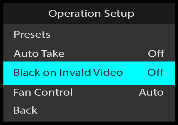
Once Black on Invalid Video is selected, the highlight bar turns from gray to cyan.
Image 5–249Operation Setup: Black on Invalid Video adjustment
Use the Adjust knob to scroll to and select either On or Off.
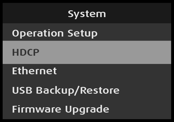
System: HDCP menu
Use System: HDCP to query and adjust the HDCP settings for all outputs, MVR output, and all inputs.
Scroll to and select HDCP on the System menu.
Image 5–250System: HDCP selection
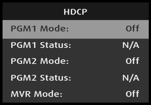
System: HDCP: Mode and Status
Note: Mode and Status selections work in the same manner for outputs and for MVR output. Mode and Status selections for inputs are slightly different. The procedure for PGM1 output is shown below.
For outputs and MVR output:
Scroll to and select PGM1 Mode on the HDCP menu.
Image 5–251System: HDCP: Mode selection
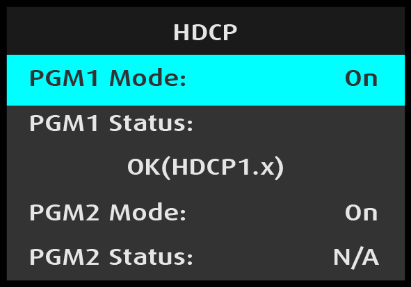
Once PGM1 Mode is selected, the highlight bar turns from gray to cyan.
Use the Adjust knob to toggle between and select either Off or On.
Image 5–252System: HDCP: Mode adjustment
When PGM1 Mode is set to “On,” the PGM1 Status line displays the HDCP status of the PGM1 output.
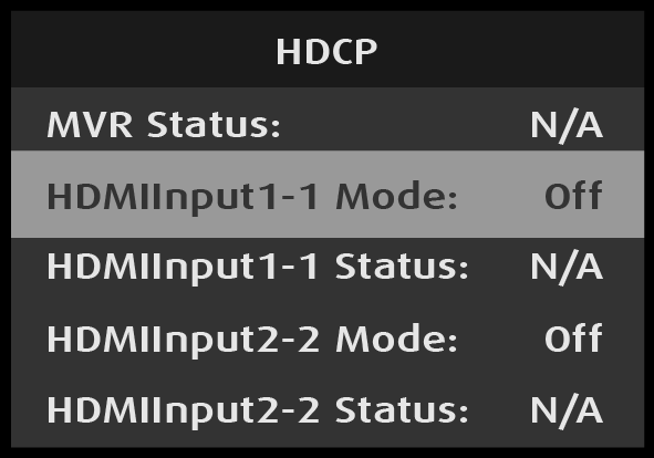
For inputs:
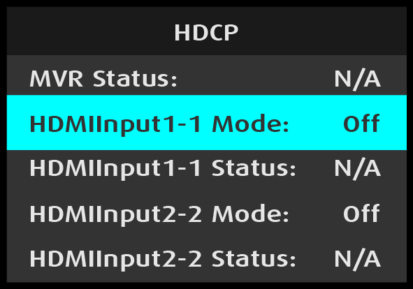
Scroll to and select HDMIInput1-1 Mode on the HDCP menu.
Image 5–253System: HDCP: Mode selection—input
Once HDMIInput1–1 is selected, the highlight bar turns from gray to cyan.
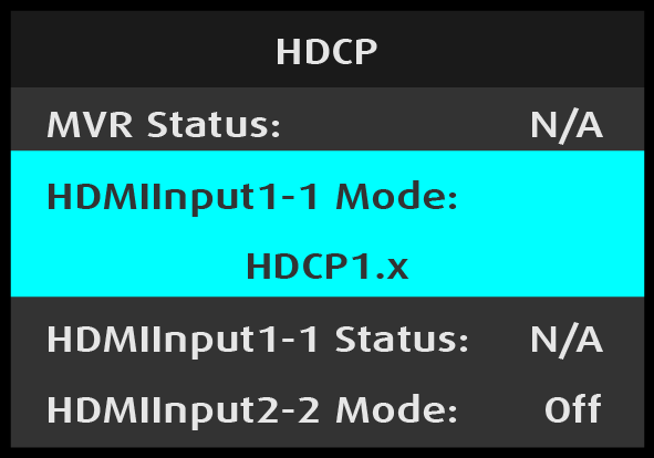
Image 5–254System: HDCP: Mode adjustment—input
Turn the Adjust knob to scroll through the available HDCP settings.
Image 5–255Adjusting HDCP input value
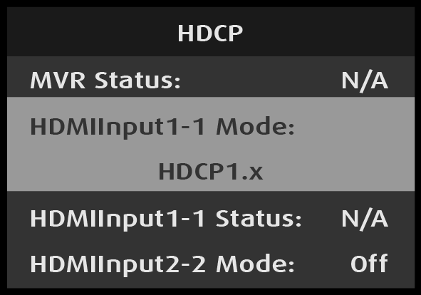
Press the Adjust knob to select the desired HDCP setting.
Image 5–256Selecting HDCP input value
After HDMIInput1-1 Mode is selected, HDMIInput1-1 Status reflects the type of HDCP authentication with the input device, if HDCP authentication is present. If no HDCP authentication is present, the HDMIInput1-1 Status reads "N/A."
System: Ethernet
Use System: Ethernet to adjust the Ethernet parameters of the system. For example, the user can set up a static IP or use DHCP (Dynamic Host Configuration Protocol).
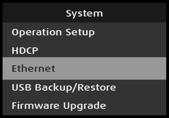
Select Ethernet on the System menu.
Image 5–257System: Ethernet selection
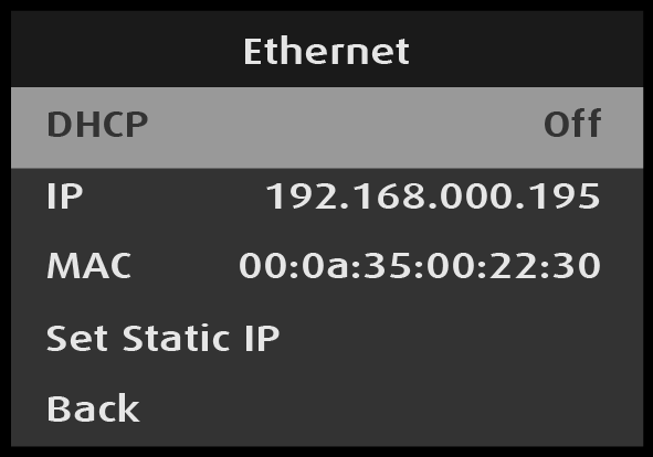
Scroll to and select the desired Ethernet parameter, for example DHCP.
Image 5–258Ethernet: DHCP selection
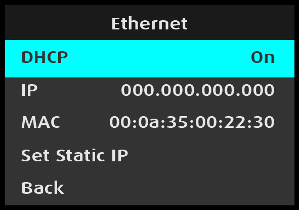
Once Ethernet parameter is selected, the highlight bar for that parameter turns from gray to cyan.
Image 5–259Ethernet: DHCP adjustment
Turn the Adjust knob to toggle between DHCP Off and On, and press the Adjust knob to select the desired value.
DHCP allows the operator to choose whether or not to use the Dynamic Host Configuration Protocol.
The default DHCP setting is Off.
When DHCP is set to On, a device can have a different IP address every time it connects to the network.
IP reports the current IP address of the system.
MAC reports the current MAC address of the system.
Set Static IP allows the operator to set the IP Address, Subnet Mask, and Gateway Mask.
To set a static IP address...
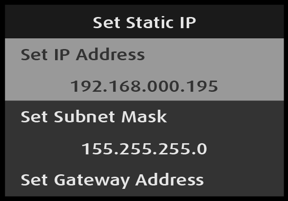
Select Set Static IP from the Ethernet menu.
Select Set IP Address from the Set Static IP menu
Image 5–260Set Static IP: Set IP Address selection
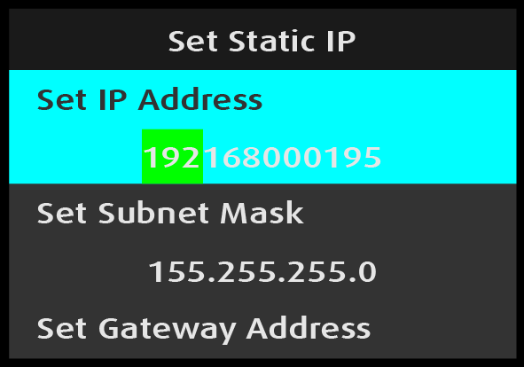
Once Set IP Address is selected, the highlight bar turns from gray to cyan, and the first portion of the IP address is highlighted in green.
Image 5–261Set Static IP: Set IP Address adjustment
Turn the Adjust knob to adjust the first portion of the IP address, and press the Adjust knob when the desired number is reached.
Repeat Step 3 for each portion of the IP address.
The Subnet Mask and the Gateway Address may be set in the same manner as the IP Address is set.
Back returns to the Ethernet menu.
Back again returns to the System menu.
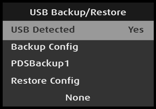
USB Backup/Restore
Use System: USB Backup/Restore to create a system backup file and to restore the system with that backup file.
Insert a FAT32-formatted USB drive in the front-panel USB port.
Select USB Backup/Restore on the System menu.
Image 5–262System: USB Backup/Restore selection
The system detects if a FAT32-formatted USB drive is in the front-panel USB port. If the system detects no USB drive in the USB port, the top line of the USB Backup/Restore menu reads, “USB Detected – No.” If the system detects a USB drive in the USB port, the top line of the USB Backup/Restore menu reads, “USB Detected – Yes.”
Image 5–263USB Backup/Restore: USB Detected—”Yes”
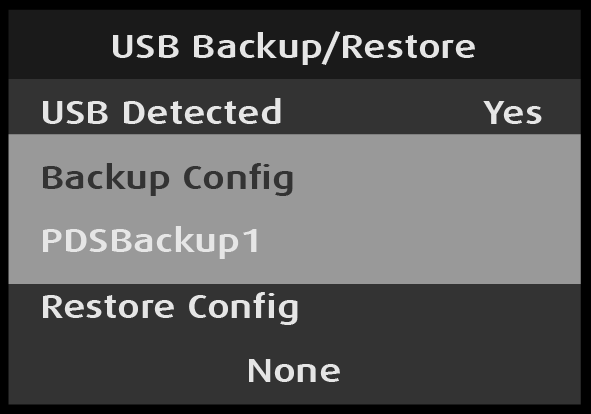
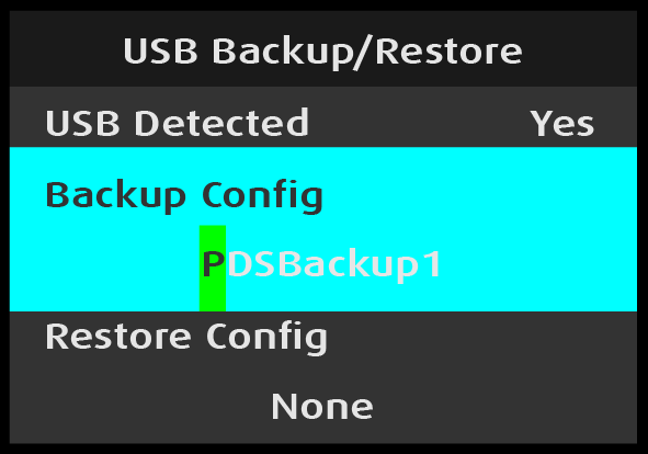
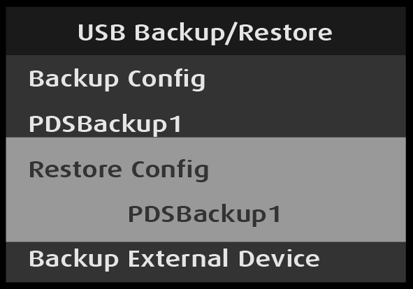
Select Backup Config on the USB Backup/Restore menu.
Once Backup Config is selected, the highlight bar turns from gray to cyan, and the first character of the backup config file name is highlighted in green.
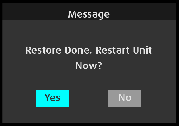
Once the Restore Config process is complete, the system displays a “Restart Unit Now?” message.
Image 5–270“Restart Unit Now?” message
Select “Yes” to restart the unit, or select “No” to return to the USB Backup/Restore menu.
USB Backup/Restore: External Device, XML, and Backup Log Files
External devices, XML, and backup log files are backed-up and restored in the same manner as backup configuration files are backed-up and restored.
System: Firmware Upgrade
Note: Upgrading the firmware through the USB port requires the “pds_update_vp.enc.xx.xx.tar.gz” file to be within a directory named EM on the USB flash drive.
Prepare a flash drive with the upgrade file.
Perform the firmware upgrade using the USB flash drive.
Prepare a flash drive with the upgrade file
Download the software upgrade for free from Barco’s website (URL: http://www.barco.com). Click on myBarco and login to get access to secured information. Registration is necessary.
Note that if you are not yet registered, click on New to myBarco and follow the instructions. With the created login and password, it is possible to login where you can download the Event Master series processor software. It is not necessary to install any other software.
Unzip directly the software upgrade downloaded from the Barco website to the USB drive. This operation automatically creates a directory named EM with the upgrade file inside (pds_update_vp.enc.xx.xx.tar.gz).
Perform the firmware upgrade using the USB flash drive
Insert the flash drive into the unit’s USB port.
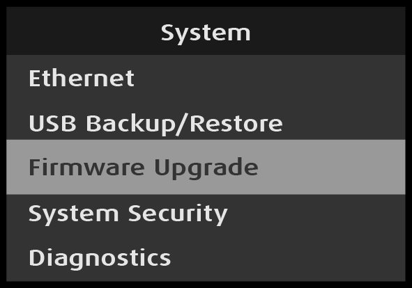
Scroll to and select Firmware Upgrade from the System menu.
Image 5–271System: Firmware Upgrade selection
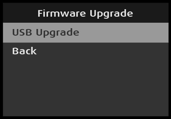
The Firmware Upgrade submenu appears.
Image 5–272Firmware Upgrade: USB Upgrade selection
Select USB Upgrade on the Firmware Upgrade menu.
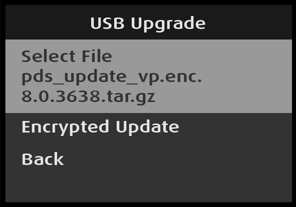
Image 5–273USB Upgrade: Select File selection
Select Select File on the USB Upgrade menu.
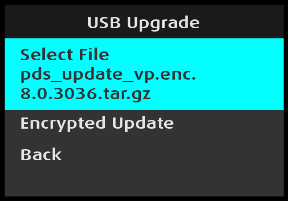
If there is more than one firmware update file in the EM directory on the USB flash drive:
Select Select File on the USB Upgrade menu.
Once Select File is selected, the highlight bar turns from gray to cyan.
Image 5–274USB Upgrade: Select File adjustment
Turn the Adjust knob to scroll through the available firmware upgrade files.
Press the Adjust knob to select the desired firmware upgrade file.
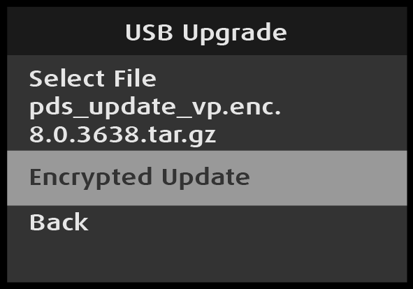
Scroll to and select Encrypted Update on the USB Upgrade menu.
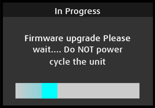
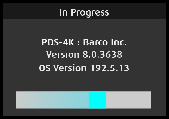
While the firmware upgrade is in progress, the system displays several messages.
Image 5–276Firmware upgrade “In Progress” message 1Image 5–277“Do NOT power cycle” messageImage 5–278Firmware upgrade “In Progress” message 2
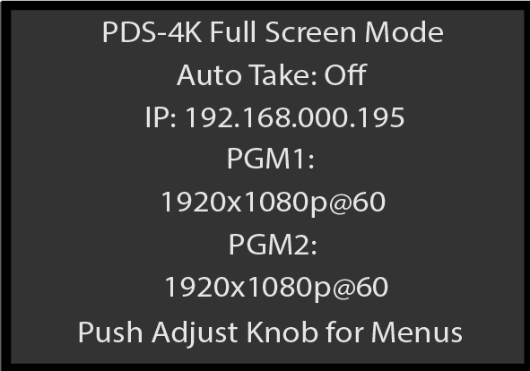
The firmware upgrade process takes about five minutes. When the firmware upgrade is complete, the system displays the Status menu.
Image 5–279Status menu after firmware upgrade
System: System Security
Use System: System Security to adjust the Admin Lock, WebApp Lock, and the Front Panel Lock.
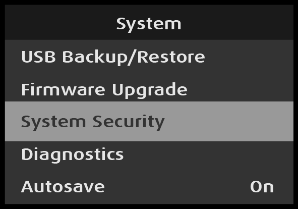
Select System Security from the System menu.
Image 5–280System menu: System Security selection
Back returns to the System menu.
System Security: Admin Lock
When the Admin Lock is enabled, Event Master Toolset users are not allowed to delete Inputs, Outputs, Destinations, Presets, User Keys, Cues, or External Devices. Users are allowed operator-level functionality to recall Presets and Cues and to transition.
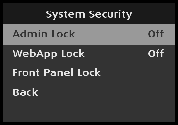
Select Admin Lock from the System Security menu.
Image 5–281System Security: Admin Lock selection
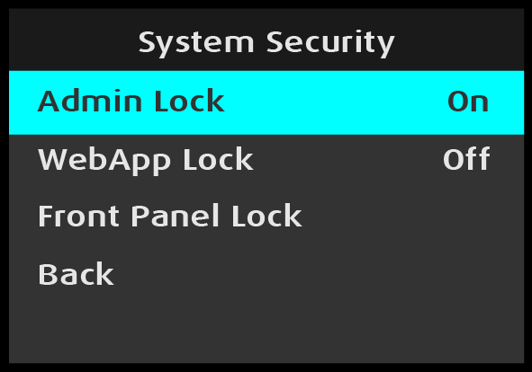
Once Admin Lock is selected, the highlight bar turns from gray to cyan.
Turn the Adjust knob to toggle Admin Lock between “On” and “Off.”
Image 5–282
Press the Adjust knob to select either “On” or “Off.”
System Security: WebApp Lock
When the WebApp Lock is off (disabled), the settings page hosted in the PDS-4K is accessible through a web browser, as well as through the Settings menu in the EMTS GUI. When the WebApp Lock is enabled, the WebApp is in read-only mode, and no settings can be changed.
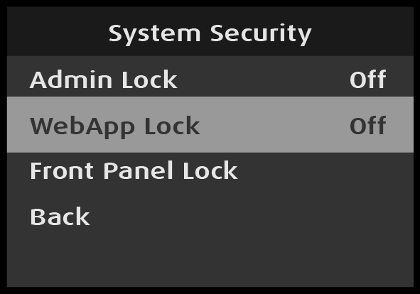
Select WebApp Lock from the System Security menu.
Image 5–283System Security: WebApp Lock selection
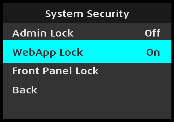
Once WebApp Lock is selected, the highlight bar turns from gray to cyan.
Turn the Adjust knob to toggle Admin Lock between “On” and “Off.”
Press the Adjust knob to select either “On” or “Off.”
System Security: Front Panel Lock
Use Front Panel Lock to lock the front-panel buttons. The user may also access Front Panel Lock through the Operation Setup submenu of the System menu.
Select Front Panel Lock from the System Security menu.
Image 5–285System Security: Front Panel Lock selection
Once Front Panel Lock is selected, the system displays the following message:
Image 5–286“Front Panel Locked” message
Press and hold the ESC button to unlock the front-panel buttons.
Once the front-panel buttons are unlocked, the system displays the Status menu.
System: Diagnostics
The Diagnostics menu allows an operator to check if the PDS-4K unit is functioning normally. Front panel and system operations can be checked. Various system temperatures can be monitored and backup log files can be saved for customer service troubleshooting.
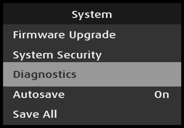
Select Diagnostics from the System menu.
Image 5–287System menu: Diagnostics selection
Scroll to and select the diagnostic to be performed.
Note: Do not perform diagnostics while running a show; the A/V outputs may be disrupted.
Back returns to the System menu.
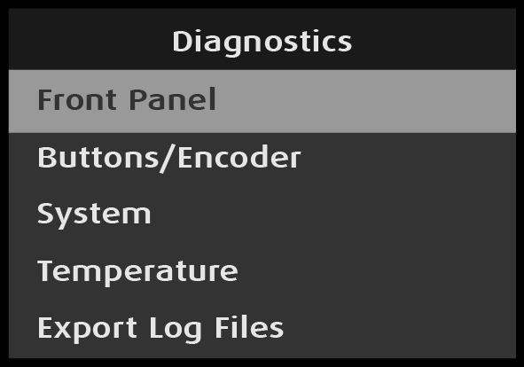
Diagnostics: Front Panel
Scroll to and select Front Panel from the Diagnostics menu.
Image 5–288Diagnostics: Front Panel selected
When Front Panel is selected, the system displays the message “Diagnostics in progress…,” and the menu display and the front-panel buttons flash red, then blue, then green.
When the front-panel diagnostic is finished, the system displays a message.
Image 5–289“Diagnostics in progress” message
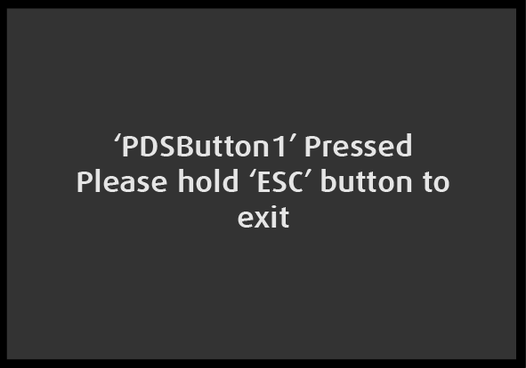
Turn the Adjust knob or press any front-panel button, for example Button #1 (the left-most button on the top row).
Image 5–290“’PDSButton1’ Pressed” message
Press and hold the ESC button to return to the Diagnostics menu.
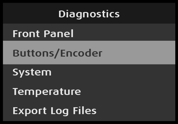
Diagnostics: Buttons/Encoder
Scroll to and select Buttons/Encoder from the Diagnostics menu.
Image 5–291Diagnostics: Buttons/Encoder selected
When Front Panel is selected, the system displays the message “Diagnostics in progress…”
Image 5–292“Diagnostics in progress” message
Turn the Adjust knob or press any front-panel button.
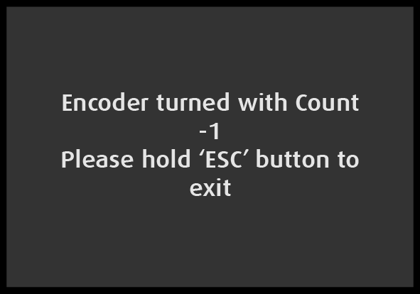
If, for example, the Adjust knob is turned, the system displays the following message.
Image 5–293“Encoder turned” message
Press and hold the ESC button to return to the Diagnostics menu.
Diagnostics: System
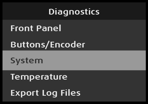
Scroll to and select System from the Diagnostics menu.
Image 5–294Diagnostics: System selected
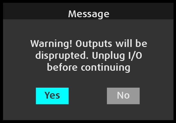
When System is selected, the system displays the “Outputs will be disrupted” warning message.
Image 5–295“Outputs will be disrupted” warning message
Disconnect all outputs.
Press the Adjust knob to select “Yes.”
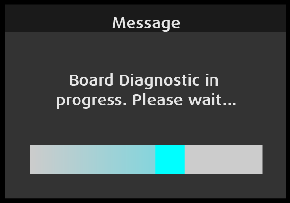
When “Yes” is selected, the system begins the board diagnostic and displays the following message.
Image 5–296“Board Diagnostic in progress” message
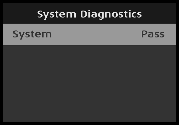
When the diagnostic has finished, the system displays the result.
Image 5–297System diagnostics result: “Pass”
Press the ESC button to return to the diagnostics menu.
Reconnect the outputs.
Diagnostics: Temperature
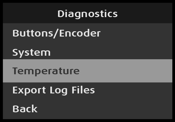
Scroll to and select Temperature from the Diagnostics menu.
Image 5–298Diagnostics: Temperature selected
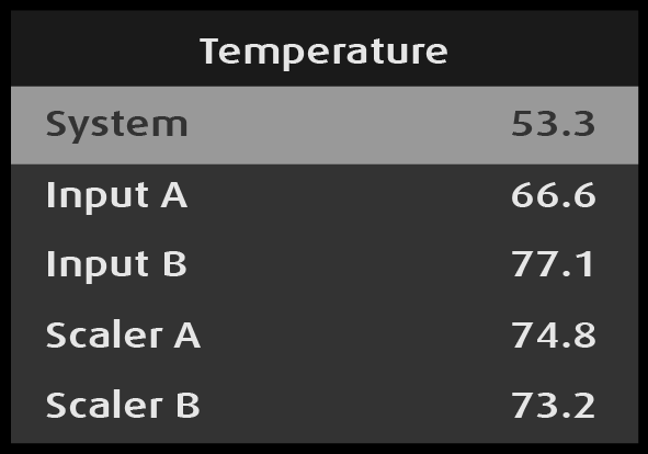
The system performs the temperature diagnostics and displays the results.
Image 5–299Temperature diagnostic results
The system displays the temperature results in °C for the following items:
System
Input A
Input B
Scaler A
Scaler B
MVR
Expansion slot
Turn the Adjust knob to scroll through the temperature diagnostic results.
Back returns to the Diagnostics menu.
Diagnostics: Export Log Files
Insert a FAT32-formatted flash drive in the front-panel USB slot.
If there is no USB drive in the USB slot when you attempt to export the log files, the system displays the message “Cannot store backup logs. USB is not connected.”
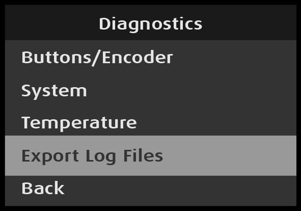
Scroll to and select Export Log Files on the Diagnostics menu.
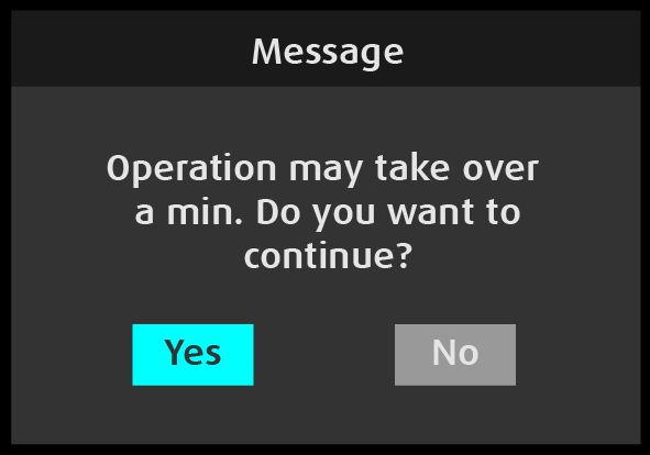
When Export Log Files is selected, the system displays the following message.
Image 5–301“Continue operation” message
Press the Adjust knob to select “Yes.”
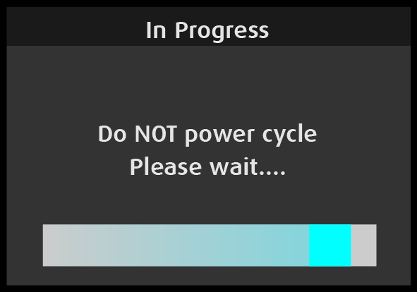
While the log files are being exported, the system displays the “Do not power cycle” message.
Image 5–302“Do not power cycle” message
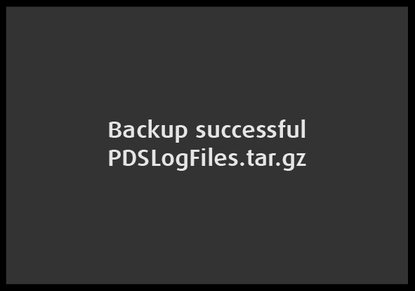
The system creates a log file called PDSLogFiles.tar.gz and places that file in the EM\Backup folder on the USB flash drive. When the log file has been created, the system flashes the following message, then returns to the Diagnostics menu.
Image 5–303“Backup successful” message
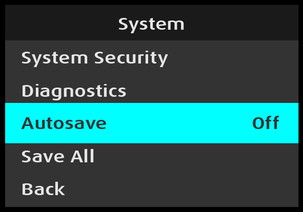
System: Autosave
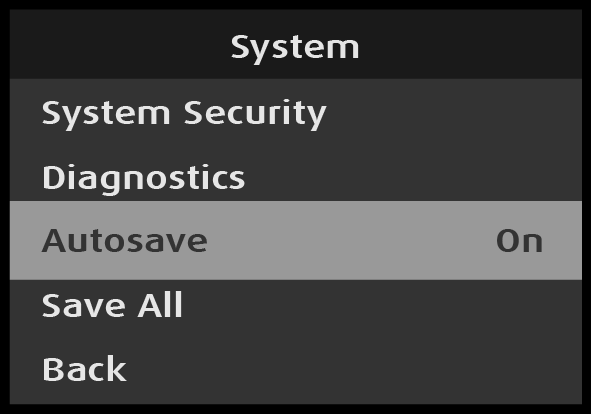
Scroll to and select Autosave on the System menu.
Image 5–304System: Autosave selection
Once Autosave is selected, the highlight bar turns from gray to cyan.
Image 5–305System: Autosave adjustment
Turn the Adjust knob to toggle between “On” and “Off.”
Press the Adjust knob to select either “On” or “Off.”
Note: The default selection for Autosave is “On.” With Autosave set to On the PDS-4K will automatically save the system state after one minute of inactivity (no button presses on the front panel). With Autosave set to Off the user will have to manually save the system state with the below Save All function in order to save all configuration settings into non-volatile memory.
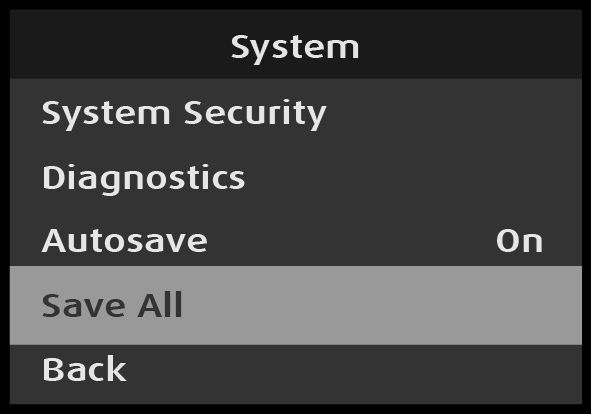
System: Save All
Use Save All to save all of the system settings.
Scroll to and select Save All on the System menu.
Image 5–306System: Save All selection
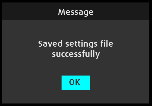
When Save All is selected, the system displays the following message.