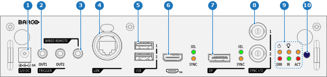
Front panel Control & Communication module
- 1
- 12V DC
- 2
- TRIGGER
- 3
- WIRED REMOTE
- 4
- LAN
- 5
- USB
- 6
- HDMI™
- 7
- DP
- 8
- SYNC I/O
- 9
- Projector status LEDs
- 10
- IR receiver
| Nr | Name | Description |
| 1 | 12V DC | 12 V DC output, maximum 1A available when projector is not in standby. |
| 2 | TRIGGER | Two 3.5 mm mini jack connectors (OUT1 & OUT2) for controlling peripherals like motorized screens, curtains etc. Give 12V DC, 0.5A (6W) output when projector is switched on. Note: If the TRIGGER outputs are loaded too heavy, there is a risk that the projector will go in reset mode, and restart. This causes no damage to the projector, but is an undesirable response. This will also happen if the startup current for the external equipment is too high, even though the nominal power consumption is less than 0,5A |
| 3 | WIRED REMOTE | Connect the RCU via a 3.5 mm mini jack with the wired remote input to control the projector without interference. |
| 4 | LAN | Standard RJ45 connector for external projector control over IP and Art-Net. |
| 5 | USB | 2 x USB 2.0 type A. These USB ports will simplify the service procedures for firmware updates or for downloading the log files without a network connection. If the only file on the USB device is the firmware file (a “*.fw” file), the projector will automatically start one of the following processes:
Note: Make sure that any used USB-stick is FAT32 compatible and contains no other files or folders. |
| 6 | HDMI™ | Standard HDMI 2.1 input port for source connection to the projector. |
| 7 | DP | Standard DisplayPort™ (1.4), for source connection to the projector. |
| 8 | SYNC I/O | BNC sync port in/out for projector control. This is mainly used in multiple projector installations with requirement of synchronization between the units. |
| 9 | Status LEDs | Projector status LEDs (see chapter “Projector status”). |
| 10 | IR | Infra Red receiver. |