Components
Front view:
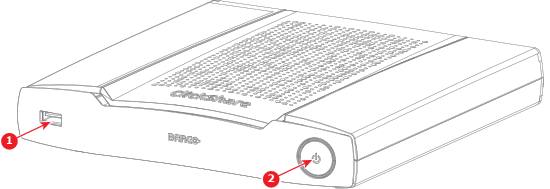
- 1
- Front USB-A port
- 2
- Power button
Back view:
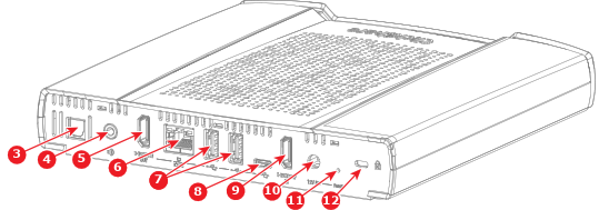
- 3
- Digital audio output port
- 4
- Analog audio output port
- 5
- HDMI™ out port
- 6
- LAN port
- 7
- Back USB-A ports
- 8
- USB-C™ port
- 9
- HDMI™ in port
- 10
- Power adapter port
- 11
- Reset button
- 12
- Kensington™ lock